Connector
a technology of connecting rods and connectors, applied in the direction of coupling device connections, optical elements, instruments, etc., can solve the problems of low degree of freedom about attaching to the case, large extension portion, and patent document 2 not disclose the measures of electromagnetic interference (emi), etc., to achieve the effect of suppressing radiating noise and improving the degree of freedom
- Summary
- Abstract
- Description
- Claims
- Application Information
AI Technical Summary
Benefits of technology
Problems solved by technology
Method used
Image

Examples
first embodiment
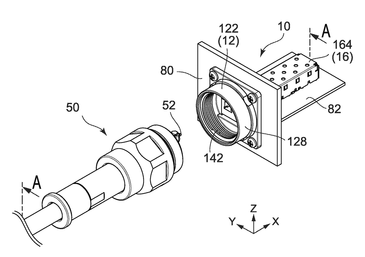
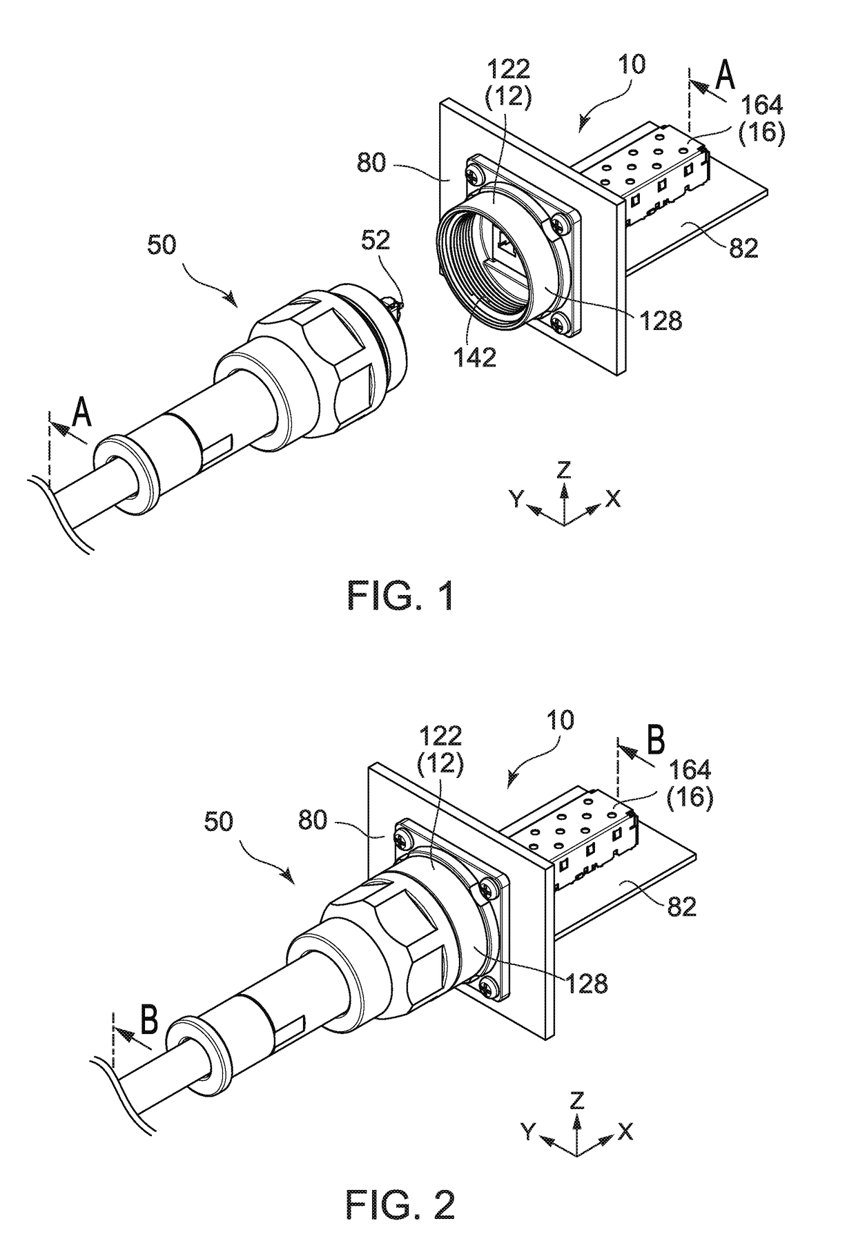
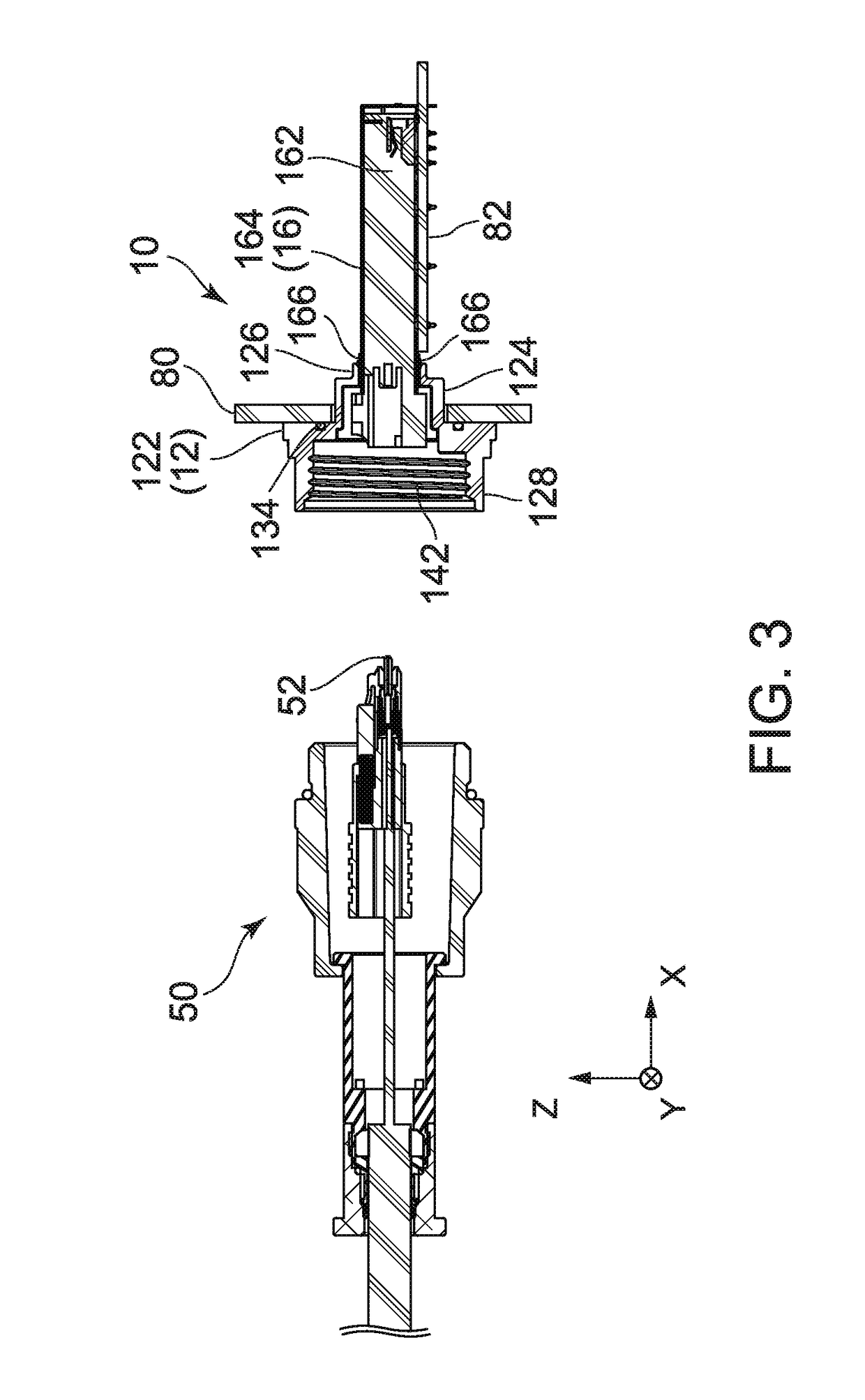
[0054]As understood from FIGS. 1 to 4, a connector 10 according to a first embodiment of the present invention is a receptacle connector which is mateable with and removable from a mating connector 50, i.e. a plug connector, along a mating direction. The connector 10 forms a connector assembly together with the mating connector 50. It should be noted that the mating direction is an X-direction in the present embodiment.
[0055]As shown in FIGS. 5 to 9, the connector 10 is provided with a receptacle 12 and an adapter 16. The receptacle 12 is attached to a case 80 of a device (not shown) from the outside or a negative X-direction of the case 80. A part of the receptacle 12 is inserted into a hole 802 formed in the case 80 and protrudes inside the case 80 or in a positive X-direction. The adapter 16 is mounted on a circuit board 82 located in the case 80. A part of the adapter 16 is positioned inside the receptacle 12. The receptacle 12 and the circuit board 82 are indirectly fixed to ea...
second embodiment
[0063]As understood from FIGS. 15 to 20, the connector 10A according to the second embodiment of the present invention is a receptacle connector which is mateable with and removable from a mating connector 50A or a plug connector along a mating direction. The mating connector 50A is different from the mating connector 50 (see FIG. 1) in structure. In this connection, the connector 10A is different from the connector 10 (see FIG. 1) according to the first embodiment in structure. Hereinafter, the description will be made about the difference between the connector 10A and the connector 10 mainly. In the following description, components of the connector 10A which are same as those of the connector 10 are denoted by the same reference signs, and their description is omitted.
[0064]As shown in FIGS. 21 to 26, the connector 10A is provided with a receptacle 12A and an adapter 16. The receptacle 12A is provided with a pair of arm portions 210. The arm portions 210 are also referred to as a...
third embodiment
[0069]As understood from FIGS. 30 to 32, the connector 10B according to the third embodiment of the present invention is receptacle connector which is mateable with and removable from a mating connector 50B or a plug connector along a mating direction. The mating connector 50B is different from the mating connector 50 (see FIG. 1) in structure. In this connection, the connector 10B is also different from the connector 10 (see FIG. 1) according to the first embodiment in structure. Hereinafter, the description will be made about the difference between the connector 10B and the connector 10 mainly. In the following description, components of the connector 10B which are same as those of the connector 10 are denoted by the same reference signs, and their description is omitted.
[0070]As understood from FIGS. 30 and 31, the connector 10B is provided with a receptacle 12B and an adapter 16. The receptacle 12B is attached to a case 80B of a device (not shown) from the outside or the negativ...
PUM
 Abstract
Description
Claims
Application Information
 - R&D
- Intellectual Property
- Life Sciences
- Materials
- Tech Scout
- Unparalleled Data Quality
- Higher Quality Content
- 60% Fewer Hallucinations
Browse by: Latest US Patents, China's latest patents, Technical Efficacy Thesaurus, Application Domain, Technology Topic, Popular Technical Reports.
© 2025 PatSnap. All rights reserved.Legal|Privacy policy|Modern Slavery Act Transparency Statement|Sitemap|About US| Contact US: help@patsnap.com