Depth mapping with a head mounted display using stereo cameras and structured light

a stereo camera and structure technology, applied in the field of three-dimensional depth mapping using structured light, can solve the problems of high implementation cost, difficulty in providing ideal beam geometry, and inability to accurately combine motion tracking and feature recognition, so as to improve tracking, and reduce the resolution of structured light pattern

Active Publication Date: 2018-06-07
META PLATFORMS TECH LLC
View PDF0 Cites 15 Cited by
  • Summary
  • Abstract
  • Description
  • Claims
  • Application Information

AI Technical Summary

Problems solved by technology

Drawbacks of such visual imaging include a requirement that the three-dimensional area is sufficiently illuminated.
Furthermore, the only features that can be tracked are features that are recognized in advance, and motion tracking combined with feature recognition may not give accurate results.
Disadvantages include the high cost of implementation, difficulties providing the ideal beam geometry, and laser typical effects such as speckle noise and the possible self-interference with beam parts reflected from objects.
Furthermore, there is no means of modulating individual bars, such as with Gray codes.
Specifically, a disadvantage of using a single source emitter such as an edge emitter laser diode is the fact that the light pattern that it produces can be controlled only as a single unit.
This means that while the light pattern can be entirely turned on, off or dimmed, it cannot be changed dynamically.
Edge-emitters cannot be tested until the end of the production process.
If the edge-emitter does not function properly, whether due to bad contacts or poor material growth quality, the production time and the processing materials have been wasted.
However, despite the above advantages, the VCSEL array is not currently used for structured light scanning systems for a number of reasons.
The multiple points and overlap between them reduce the detection performance in high-density areas in the light pattern and restrict the use of various diffractive design techniques that requires a pre-defined Gaussian beam.

Method used


Image

  • Depth mapping with a head mounted display using stereo cameras and structured light
  • Depth mapping with a head mounted display using stereo cameras and structured light
  • Depth mapping with a head mounted display using stereo cameras and structured light

Examples


Embodiment Construction

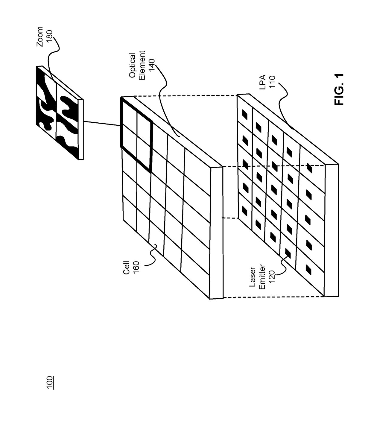
[0041]FIG. 1 is a schematic diagram of a structured light emitter (SLE) 100 for 3D tracking using patterned light according to an embodiment. The SLE 100 includes a light producing array (LPA) 110 configured to emit patterned light such as structured light. In one or more embodiments, the LPA 110 is an array of lasers comprising a plurality of light sources such as laser emitters 120. The SLE 100 also includes an optical element 140. In various embodiments, the optical element 140 comprises a plurality of cells 160. Each cell 160 is configured as a diffractive element and is aligned with a particular laser emitter 120, so that individual cells of the plurality of cells 160 modulate the light emitted by a respective laser emitter 120. Zoom 180 of the cells 160 shows four cells 160 each with a unique diffractive pattern. The SLE 100 may generate a structured light pattern from the LPA 110. In one or more embodiments, the generated structured light pattern is projected into a 3D space ...


PUM


Abstract

A tracking system generates a structured light pattern in a local area. The system includes an array of lasers that generate light. The array of lasers includes a plurality of lasers and an optical element. The plurality of lasers are grouped into at least two subsets of lasers, and each of the at least two subsets of lasers is independently switchable. The optical element includes a plurality of cells that are each aligned with a respective subset of the array of lasers. Each cell receives light from a corresponding laser of the array of lasers, and each cell individually applies a modulation to the received light passing through the cell to form a corresponding portion of the structured light pattern that is projected onto a local area.

Description

CROSS-REFERENCE TO RELATED APPLICATION[0001]This application is a continuation of U.S. application Ser. No. 15 / 077,540, filed Mar. 22, 2016, which claims the benefit of U.S. Provisional Patent Application No. 62 / 136,549, filed Mar. 22, 2015, the disclosure of which is hereby incorporated by reference in its entirety. Additionally, the following applications are hereby incorporated by reference as if fully set forth herein, namely U.S. patent application Ser. No. 13 / 497,589, filed on Sep. 19, 2010, International Patent Application No. WO2013 / 088442 filed Dec. 13, 2012, U.S. Provisional Patent Application No. 61 / 926,476, filed on Jan. 13, 2014, U.S. Provisional Patent Application No. 62 / 035,442, filed on Aug. 10, 2014.BACKGROUND[0002]The present disclosure generally relates to three-dimensional depth mapping using structured light, and more particularly, but not exclusively, to a system for tracking.[0003]Tracking of styluses and fingers in a three-dimensional field in front of the co...

Claims


Application Information

Patent Timeline
Patent Type & Authority Applications(United States)
IPC IPC(8): G06F3/03G06V10/145H01S5/00H01S5/42H04N13/00
CPCH04N13/25H04N13/254H04N13/044H04N13/0253H04N13/344H04N2013/0081H01S5/423H01S5/0085G06F3/0317H04N13/025G06F3/0325G01N21/8806G06V40/28G06V10/145G06V2201/12H04N13/271
Inventor ROMANO, NITAYGROSSINGER, NADAVALPERN, YAIRALON, EMILRAZ, GUY
Owner META PLATFORMS TECH LLC
Why Eureka
Try Eureka