
Multi-stage axial flow cyclone separator

a cyclone separator and axial flow technology, applied in combination devices, single direction vortex, centrifugal force sediment separation, etc., can solve the problems of low separation efficiency, limited separation efficiency, and inability to increase separation efficiency

Active Publication Date: 2018-06-14
YAOVAPHANKUL LUXNARA
View PDF12 Cites 0 Cited by
  • Summary
  • Abstract
  • Description
  • Claims
  • Application Information

AI Technical Summary

Benefits of technology

The present invention is a multi-stage cyclone separator that creates a swirling flow to separate fluids. It includes a cylindrical transmission base with an internal cavity and a side penetrable hole for introducing fluid from the outside. The penetrable hole has a curved edge in a convex curve that deflects the fluid to flow along its surface, creating a force vortex. The swirl generating chamber has a throat to promote the generation of swirling flow and induce the fluid to flow in a laminar manner. The apparatus is inserted into a cylindrical tube of a cyclone separator with a gap between them. The technical effects of the invention are improved separation efficiency and reduced pressure drop.

Problems solved by technology

The present invention is about a new cyclone separator that can better separate mixed fluids that conventional cyclone separators cannot efficiently separate. The technical problem that this invention solves is the limitation of conventional cyclone separators in separating heterogeneous mixtures of fluids in continuous phase. The new cyclone separator is a multi-stage axial flow cyclone separator that can increase separation efficiency by increasing swirling velocity and residence time.

Method used


Image

  • Multi-stage axial flow cyclone separator
  • Multi-stage axial flow cyclone separator
  • Multi-stage axial flow cyclone separator

Examples


Embodiment Construction

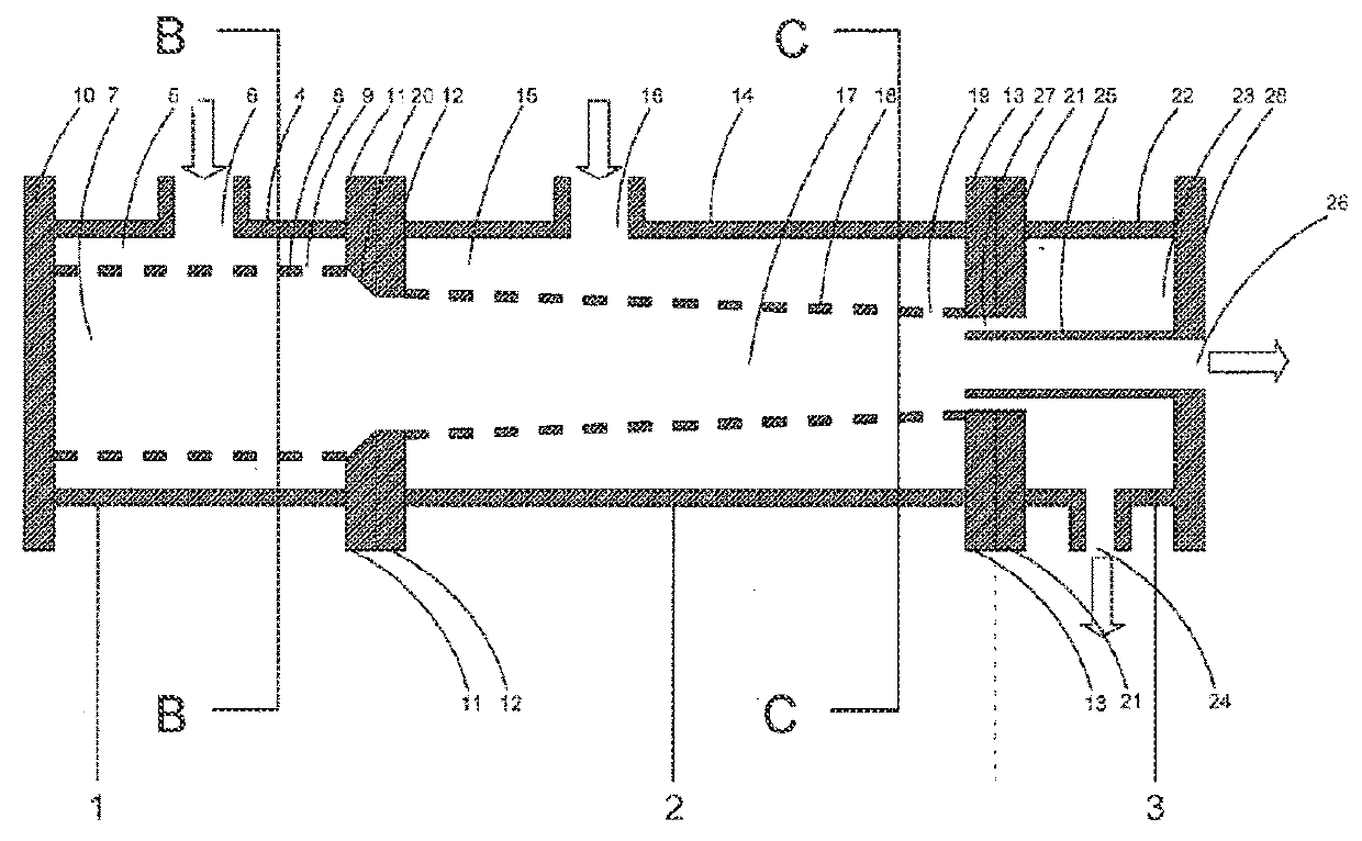
[0023]According to FIGS. 1A-C, the multi-stage axial flow cyclone separator according to the present invention comprises a primary swirl creating section 1 connected to a swirl acceleration section 2 and connected to a fluid separation section 3 wherein

[0024]the primary swirl creating section 1 comprises an outer structure of the primary swirl creating section 4 formed as an outer structure having an open end and an inside cavity for fluid distribution 5 for distribution fluid received from a primary fluid inlet 6 wherein

[0025]the primary fluid inlet 6 is formed as at least one hole on a lateral side of the outer structure of the primary swirl creating section 4 or as at least one tube extending from lateral side of the outer structure of the primary swirl creating section 4 for serving as ports for transferring fluid from the outside to the fluid distribution chamber 5 for transferring to a swirl generating chamber 7 of an apparatus for creating a swirling flow 8 mounted inside the...


PUM

PropertyMeasurementUnit
Diameteraaaaaaaaaa
Velocityaaaaaaaaaa

Abstract

A multi-stage axial flow cyclone separator comprising a primary swirl creating section, a swirl acceleration section, and a fluid separation section is disclosed. A fluid transfer tube is mounted axially in the middle of the inside of an outer structure of the fluid separation section for separating the light phase fluid and transferring it through an open end. Additionally, the swirl acceleration section and the fluid separation section can be annexed to a multi-stage axial flow cyclone separator according to the present invention to increase the velocity of the swirl and to increase the residence time to improve separation efficiency as desired.

Description


Claims


Application Information

Patent Timeline
Owner YAOVAPHANKUL LUXNARA
Learn More