Thin-plate ln optical control device

Active Publication Date: 2018-06-14
SUMITOMO OSAKA CEMENT CO LTD
View PDF2 Cites 5 Cited by
  • Summary
  • Abstract
  • Description
  • Claims
  • Application Information

AI Technical Summary

Benefits of technology

[0017]According to the aspect of the invention, in the thin-plate LN optical control device including: the thin-plate LN optical waveguide element which includes the optical waveguide formed by thermal diffusion of Ti in the LN substrate, and the control electrode that is formed on the substrate and is configured to control a light wave propagating through the optical waveguide, and in which at least a part of the substrate is thinned; a

Problems solved by technology

When being left as is in a moisture-containing atmosphere, an adhesive force of an organic material such as the adhesive may deteriorate.
In addition, in a case where application of a voltage is performed continuously in the moisture-containing atmosphere, disconnection or short-circuiting due to migration may occur in the electrical interconnection.
However, there is a concern that an LN substrate t

Method used


Image

  • Thin-plate ln optical control device
  • Thin-plate ln optical control device
  • Thin-plate ln optical control device

Examples


Embodiment Construction

[0029]Hereinafter, a thin-plate LN optical control device of the invention will be described in detail.

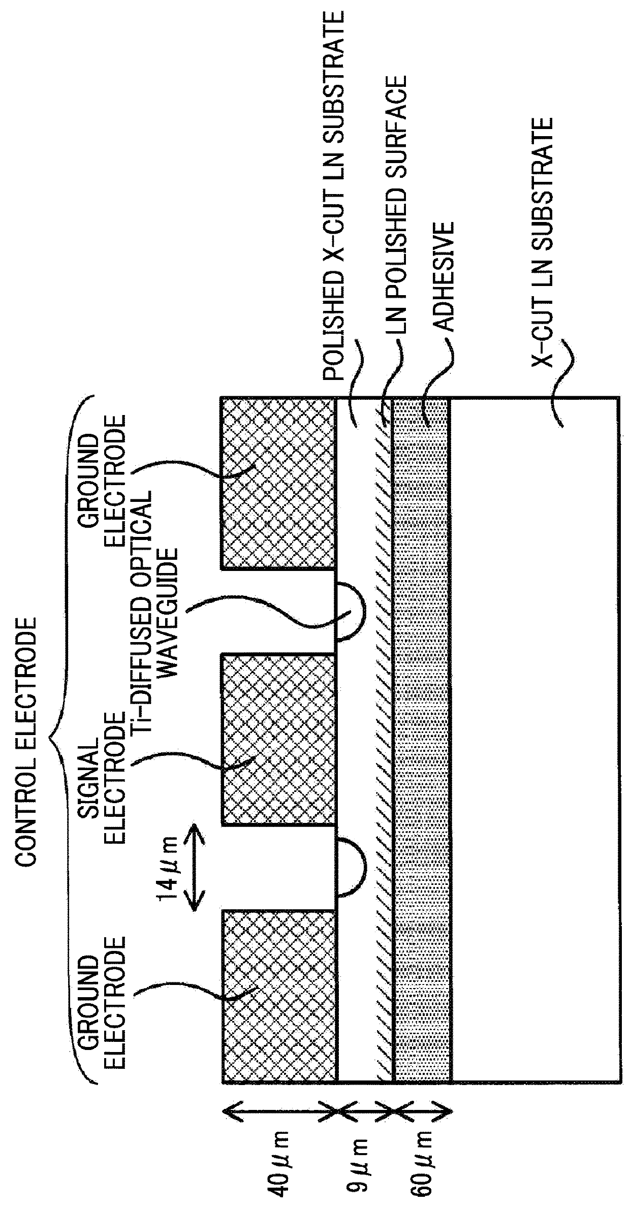
[0030]According to the invention, there is provided a thin-plate LN optical control device including: a thin-plate LN optical waveguide element which includes an optical waveguide formed by thermal diffusion of Ti and a control electrode configured to control a light wave propagating through the optical waveguide in a substrate made of lithium niobate, and in which at least a part of the substrate is thinned; and a housing that accommodates the thin-plate LN optical waveguide element in an air-tight sealing manner. Oxygen is contained in a filler gas inside the housing.

[0031]“Thinning” in the invention represents a state in which the thickness of at least a part of a substrate is made to be small by mechanical processing such as polishing and cutting. The “thinning” includes not only a state in which the entirety of the substrate is made to be thin but also a state in which a ridge...


PUM


Abstract

A thin-plate LN optical control device includes: a thin-plate LN optical waveguide element which includes an optical waveguide formed by thermal diffusion of Ti in a substrate made of lithium niobate, and a control electrode that is formed on the substrate and is configured to control a light wave propagating through the optical waveguide, and in which at least a part of the substrate is thinned; and a housing that accommodates the thin-plate LN optical waveguide element in an air-tight sealing manner. Oxygen is contained in a filler gas inside the housing.

Description

CROSS-REFERENCE TO RELATED APPLICATIONS[0001]This application claims the benefit of Japanese Patent Application No. 2016-241813 filed Dec. 14, 2016, the disclosure of which is herein incorporated by reference in its entirety.BACKGROUND OF THE INVENTIONField of the Invention[0002]The present invention relates to an LN optical control device including an LN optical waveguide element in which an optical waveguide and a control electrode configured to control a light wave that propagates through the optical waveguide are formed in a substrate that is formed by using lithium niobate (LN), and a housing that accommodates the LN optical waveguide element in an air-tight sealing manner, and particularly to, an LN optical control device (referred to as a thin-plate LN optical control device) that uses the LN optical waveguide element that is thinned.Description of Related Art[0003]In an optical communication field or an optical measurement field, there is known an optical control device that...

Claims


Application Information

Patent Timeline
IPC IPC(8): G02F1/03G02B6/122G02B6/13G02F1/225G02F1/035
CPCG02F1/0316G02B6/122G02B6/13G02F1/2257G02F1/0353G02F1/0305G02F1/035G02F1/225G02B6/30G02B6/1342G02F1/03
Inventor KONDOU, KATSUTOSHINAKANO, KIYOTAKAMURAKAMI, EIJI
Owner SUMITOMO OSAKA CEMENT CO LTD
Why Eureka
Try Eureka