Dielectric lens

Active Publication Date: 2020-04-30
MURATA MFG CO LTD
View PDF0 Cites 1 Cited by
  • Summary
  • Abstract
  • Description
  • Claims
  • Application Information

AI Technical Summary

Benefits of technology

The present patent can offer dielectric lenses that are easy to produce in large quantities.

Problems solved by technology

If these holes are formed by drilling, the processing time is long, and resulting low productivity is a problem.
Thus, if the discs are formed by, for example, injection molding, the large number of holes positioned in the outer regions hinder the flow of resin, and resulting difficulty in molding is a problem.

Method used


Image

  • Dielectric lens
  • Dielectric lens
  • Dielectric lens

Examples


first embodiment

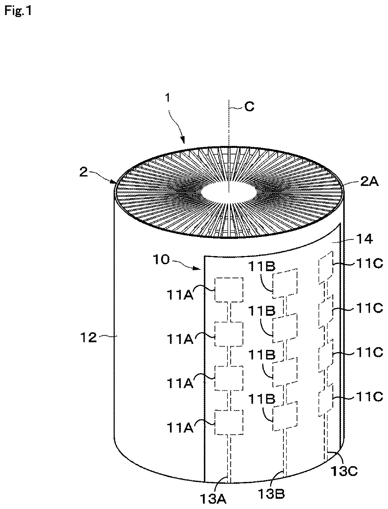
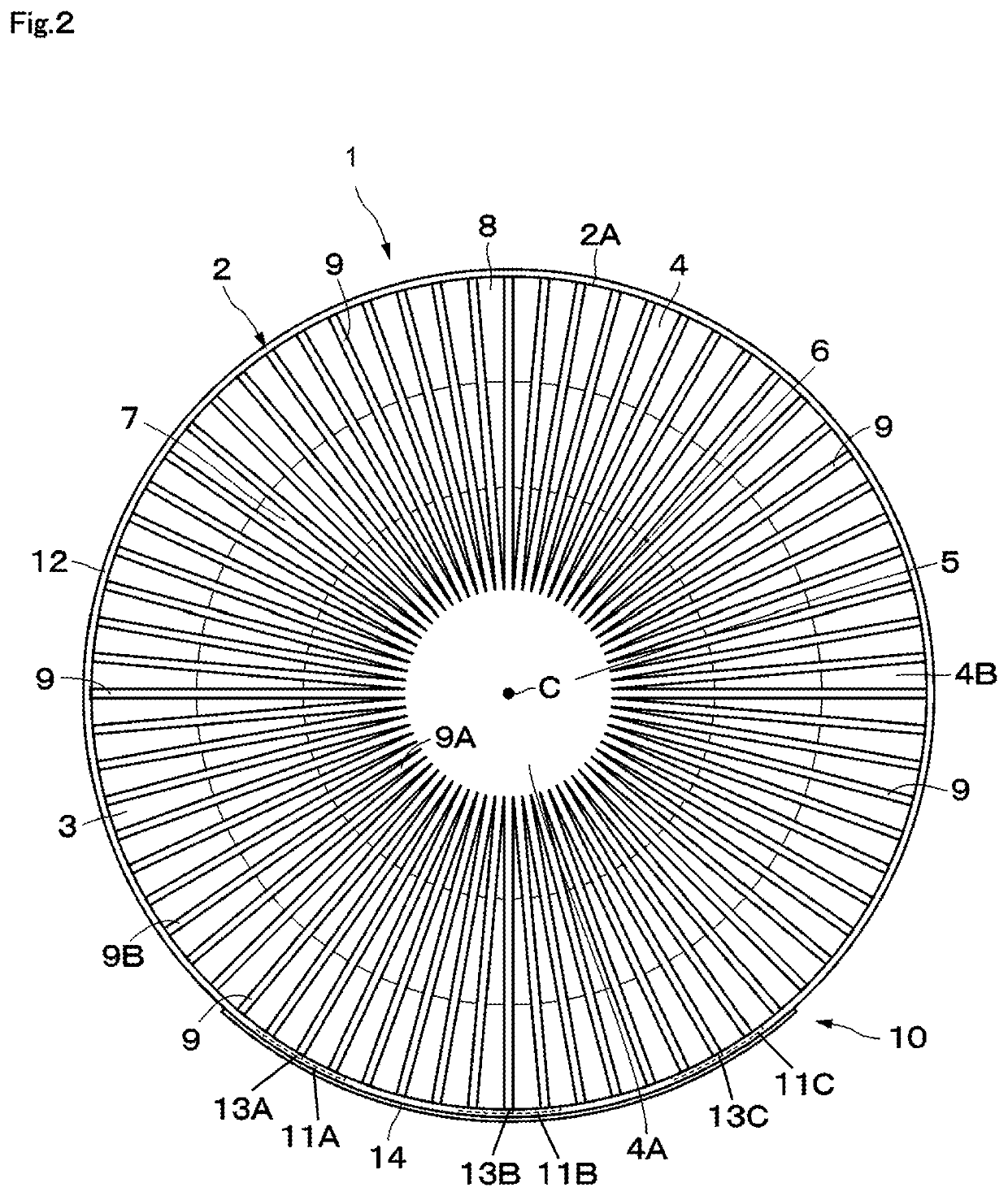
[0027]FIGS. 1 to 10 illustrate a Luneburg lens antenna device 1 (hereinafter referred to as antenna device 1) according to a The antenna device 1 includes a dielectric lens 2 and an array antenna 10.

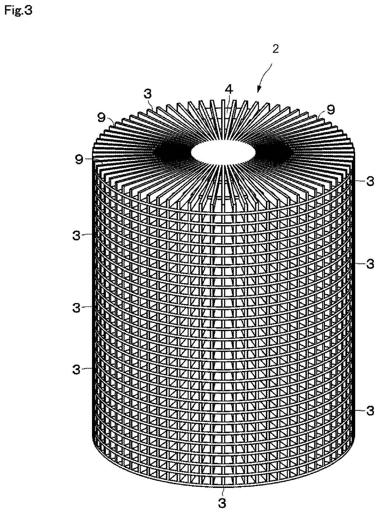
[0028]The dielectric lens 2 forms a cylindrical shape having distribution of permittivity varying with respect to the radial direction. As illustrated in FIGS. 3 to 7, the dielectric lens 2 is a laminate of a plurality of disc members 3 having the distribution of permittivity varying with respect to the radial direction. The disc members 3 are integrally formed from a resin material that allows injection molding and that has relative permittivity near two (e.g., polypropylene). The plurality of disc members 3 have the same outer diameter dimension and form a cylindrical laminate.

[0029]As illustrated in FIG. 7, each of the disc members 3 includes a planar section 4 and fin sections 9. In the planar section 4, a thickness dimension Tp4 of a radially outer area 4B is smaller than a thickne...

second embodiment

[0059]As in a second variation illustrated in FIG. 16, a disc member 41 may have a through hole 42 at the center of the planar section 4. In this case, in the state where a plurality of disc members 41 are laminated, a core member 43 made of the same dielectric material as that of the planar section 4 is placed in the through holes 42. In this case, the centers of the plurality of disc members 41 can be easily aligned by the use of the core member 43. This configuration is also applicable to the

[0060]Moreover, in the above-described first embodiment, the dielectric lens 2 has a cylindrical shape formed by the laminate of the disc members 3 having the same outer diameter dimension. The present disclosure is not limited to this example. As in a third variation illustrated in FIG. 17, for example, a plurality of disc members 52 similar to the disc members 3 may be formed with different outer diameter dimensions. The laminate of the plurality of disc members 52 with different outer diam...


PUM


Abstract

A Luneburg antenna device includes a dielectric lens and an array antenna. The dielectric lens is a laminate of a plurality of disc members having distribution of permittivity varying with respect to its radial direction. Each of the disc members includes a planar section in which a thickness dimension of a radially outer area is smaller than a thickness dimension of a radially inner area and a fin section which extends in a radial manner from a central portion of the planar section toward a radially outer side and in which a radially inner area and a radially outer area have the same thickness dimension.

Description

[0001]This is a continuation of International Application No. PCT / JP2018 / 022725 filed on Jun. 14, 2018 which claims priority from Japanese Patent Application No. 2017-128878 filed on Jun. 30, 2017. The contents of these applications are incorporated herein by reference in their entireties.BACKGROUNDTechnical Field[0002]The present disclosure relates to a dielectric lens for concentrating high-frequency radio waves, such as millimeter waves.[0003]A known example of a dielectric lens is formed of a laminate of a plurality of discs made of a dielectric material (see, for example, Non Patent Document 1). In the dielectric lens described in Non Patent Document 1, each of the discs has multiple holes, and the density of the holes in its radially outer area is higher than that in its radially inner area. Thus, the disc has permittivity distribution with respect to the radial direction.[0004]Non Patent Document 1: S. Rondineau, M. Himidi, J. Sorieux, “A Sliced Spherical Luneburg Lens,” IEEE...

Claims


Application Information

Patent Timeline
IPC IPC(8): H01Q15/08
CPCH01Q15/08H01Q21/20H01Q15/10H01Q21/0037H01Q25/007H01Q15/02
Inventor NISHIDA, HIROSHIKUBO, RYOICHI
Owner MURATA MFG CO LTD
Why Eureka
Try Eureka