
Methods and systems for generating wind turbine control schedules

a technology of control schedule and wind turbine, applied in the direction of active/predictive/anticipative control, motors, motor life prolonging, etc., can solve the problems of fatigue damage, affecting the accumulation rate of damage, and the rate of wear or accumulation of damage is many times higher

Active Publication Date: 2018-06-21
VESTAS WIND SYST AS
View PDF1 Cites 21 Cited by
  • Summary
  • Abstract
  • Description
  • Claims
  • Application Information

AI Technical Summary

Benefits of technology

The patent is about wind turbines and their design. It explains that wind turbines are designed to operate at a specific power output, called the rated power, and that they are meant to have a lifetime of 20 to 25 years. The patent also mentions software tools called site check tools, which are used to simulate the operation of wind turbines and determine their characteristics. These tools can use data from pre-construction or commissioning sensors, as well as operational data from similar turbines or power plants. Overall, the patent explains how wind turbines are designed and how they can be tested through software tools.

Problems solved by technology

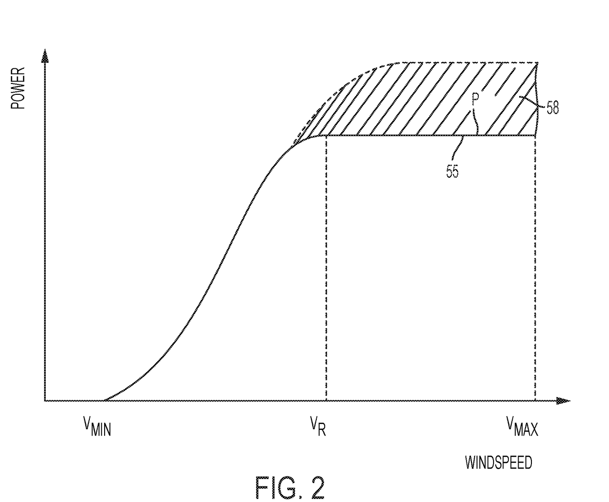
The rate of wear, or accumulation of damage, tends to increase as generated power increases.
Wind conditions also affect rate of accumulation of damage.
For some mechanical components, operation in very high turbulence causes a rate of accumulation of fatigue damage that is many times higher than in normal turbulence.
For some electrical components, operation at very high temperatures, which may be caused by high ambient temperatures, causes a rate of accumulation of fatigue damage, such as insulation breakdown rate, that is many times higher than in normal temperatures.
An increase in speed demand, torque demand and / or generator current demand increases additional power produced by over-rating, whereas a decrease in speed, torque and / or generator current demand decreases additional power produced by over-rating.
Over-rating causes higher wear or fatigue on components of the wind turbine, which may result in early failure of one or more components and require shut down of the turbine for maintenance.
Whilst over-rating allows turbine operators to increase AEP and to otherwise modify power generation to suit their requirements there are several problems and drawbacks associated with over-rating wind turbines.

Method used


Image

  • Methods and systems for generating wind turbine control schedules
  • Methods and systems for generating wind turbine control schedules
  • Methods and systems for generating wind turbine control schedules

Examples


first example

[0201]According to a first example, a control schedule is produced that can be used to control a wind turbine. A relative schedule may be defined, and one or more of a minimum wind turbine life or a maximum number of major component replacements may be defined. The schedule is then adjusted to ensure that the fatigue lifetime of the turbine meets the target lifetime whilst maximising AEP.

[0202]A wind turbine is operated according to one of the over-rating control techniques described herein using an over-rating controller, which may be implemented by the wind turbine controller.

[0203]Lifetime Usage Estimators (LUEs) may be used to determine and monitor the lifetime usage of components. Lifetime Usage Estimators may be used in ensuring the fatigue load limits of all turbine components remain within their design lifetimes. The loads a given component experiences (be they bending moments, temperatures, forces or motions for example) may be measured and the amount of component fatigue l...

second example

[0216]A second example is provided for carrying out a more general optimisation process, which may be used to carry out similar sorts of optimisation to that described above, as well as other more general optimisations. The optimisation process of the second example may be carried out by a controller applying an optimisation scheme.

[0217]A full financial cost, or levelised cost of energy (LCoE), model of the turbine is included, and used either in off-line calculations prior to installation of an over-rating control system, or used online as part of the wind turbine controller or wind power plant controller. Use of the LCoE model allows optimisation of the over-rating strategy and may also factor in replacement of main components based upon the cost of doing so. As used herein, the term “Levelised Cost of Energy” refers to a measure of the cost of energy from a turbine that is calculated by dividing the lifetime costs of the turbine by the lifetime energy output of the turbine.

[0218...


PUM


Abstract

A method of generating a control schedule for a wind turbine is provided, the control schedule indicating how the turbine maximum power level varies over time, the method comprising: receiving input indicative of a target minimum wind turbine lifetime; determining a value indicative of the current remaining fatigue lifetime of the wind turbine or one or more turbine components, based on measured wind turbine site and / or operating data; and varying a parameter of an initial predefined control schedule that specifies how the turbine maximum power level varies over time. The parameter is varied by: (i) adjusting the parameter of the initial predefined control schedule; (ii) estimating the future fatigue lifetime consumed by the wind turbine or the one or more turbine components, over the duration of the varied control schedule, based upon the varied control schedule; and (iii) repeating steps (i) and (ii) until the estimated future fatigue lifetime consumed by the wind turbine or each of the one or more turbine components is sufficient to allow the target minimum wind turbine life to be reached.

Description

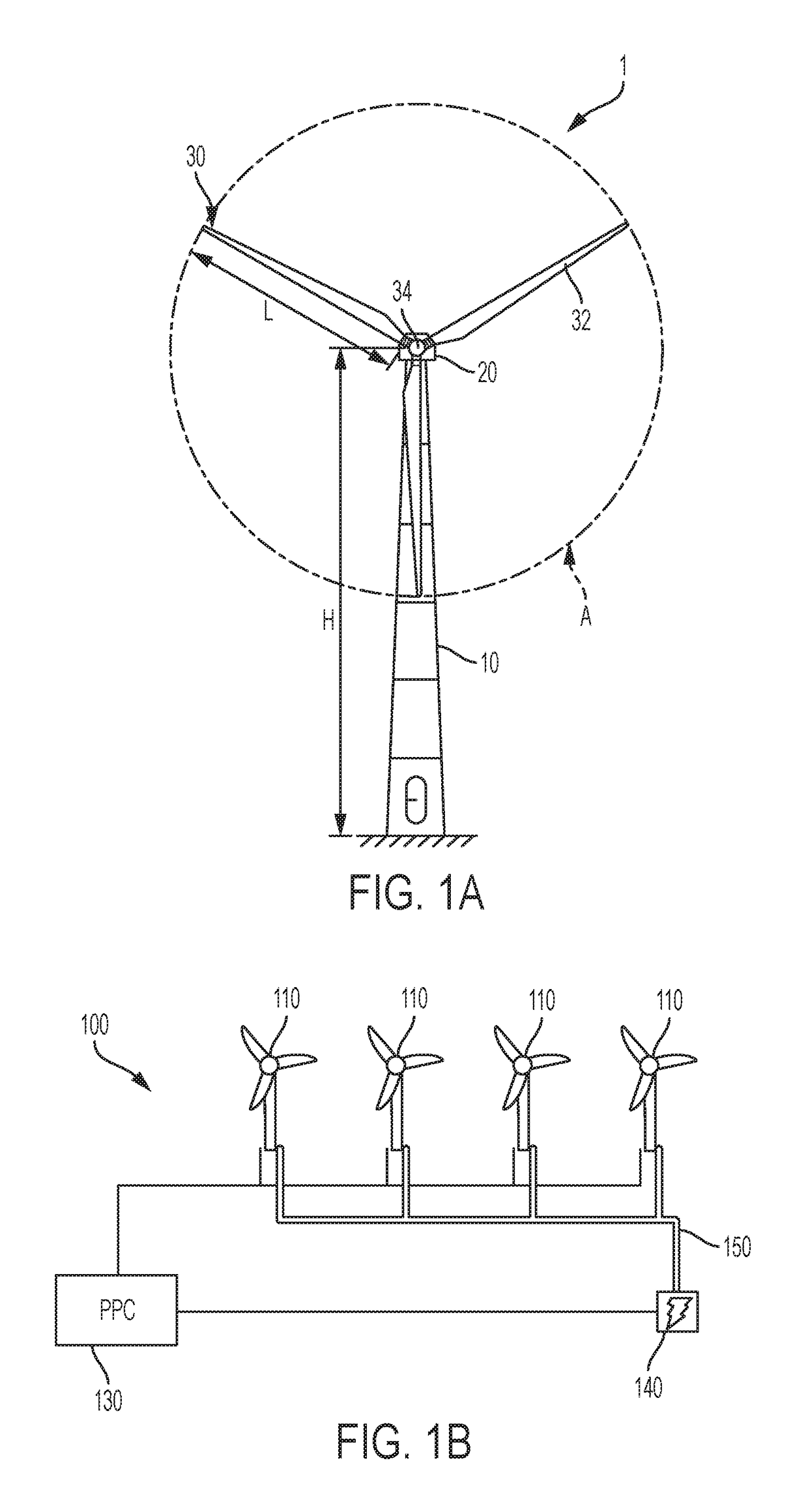
[0001]Embodiments of the present invention relate to methods and systems for determining a control schedule for wind turbine power output.[0002]FIG. 1A illustrates a large conventional wind turbine 1, as known in the art, comprising a tower 10 and a wind turbine nacelle 20 positioned on top of the tower 10. The wind turbine rotor 30 comprises three wind turbine blades 32 each having a length L. The wind turbine rotor 30 could comprise another number of blades 32, such as one, two, four, five, or more. The blades 32 are mounted on a hub 34 which is located at a height H above the base of the tower. The hub 34 is connected to the nacelle 20 through a low speed shaft (not shown) extending from the front of the nacelle 20. The low speed shaft drives a gearbox (not shown) which steps up the rotational speed and, in turn, drives an electrical generator within the nacelle 20 for converting the energy extracted from the wind by the rotating blades 32 into electrical power output. The wind t...

Claims


Application Information

Patent Timeline
IPC IPC(8): F03D7/02F03D7/04F03D80/50F03D17/00G05B19/042
CPCF03D7/0292F03D7/046F03D80/50F03D17/00F03D7/048G05B19/042F05B2270/332F05B2270/335F05B2270/1033F05B2270/404F05B2270/109F05B2240/912G05B2219/2619Y02E10/728Y02E10/72
Inventor SPRUCE, CHRIS
Owner VESTAS WIND SYST AS
Learn More