Variable capacity compressor

Active Publication Date: 2018-07-05
VALEO JAPAN CO LTD
View PDF11 Cites 1 Cited by
  • Summary
  • Abstract
  • Description
  • Claims
  • Application Information

AI Technical Summary

Benefits of technology

[0026]As described thus far, according to the present invention, in the variable capacity compressor configured to adjust a pressure of a control pressure chamber by adjusting the opening degree of the supply passage configured to cause the discharge chamber and the control pressure chamber to communicate with each other by the first control valve, and adjusting the opening degree of the bleed passage causing the control pressure chamber and the inlet chamber to communicate with each other by the second control valve, wherein the second control valve includes: a spool housing recess formed on the bleed passage, a spool housed in the spool housing recess and configured to be movable to open and close the bleed passage; a back pressure chamber segmentalized in the spool housing recess behind the spool; and biasing means configured to bias the spool in an opening direction of the bleed passage, the supply passage being connected on a downstream side with respect to the first control valve to the back pressure chamber, and wherein the back pressure chamber of the spool housing recess is configured to be connected selectively to the discharge chamber or the inlet chamber by the first control valve, so that the pressure in the back pressure chamber may be discharged to the inlet chamber in a rapid manner by connecting the back pressure chamber to the inlet chamber via the first control valve at the time of start-up, so that the start-up performance of the compressor may be improved.
[0027]In addition, when the stroke is reduced in which the supply passage is opened by the first valve portion of the first control valve, the bleed passage may be close

Problems solved by technology

Therefore, a problem is known in that the pressure in the control pressure chamber is not lowered until the entire liquid refrigerant is vapor

Method used


Image

  • Variable capacity compressor
  • Variable capacity compressor
  • Variable capacity compressor

Examples


Example

[0038]Referring now to the attached drawings, embodiments of the present invention will be described.

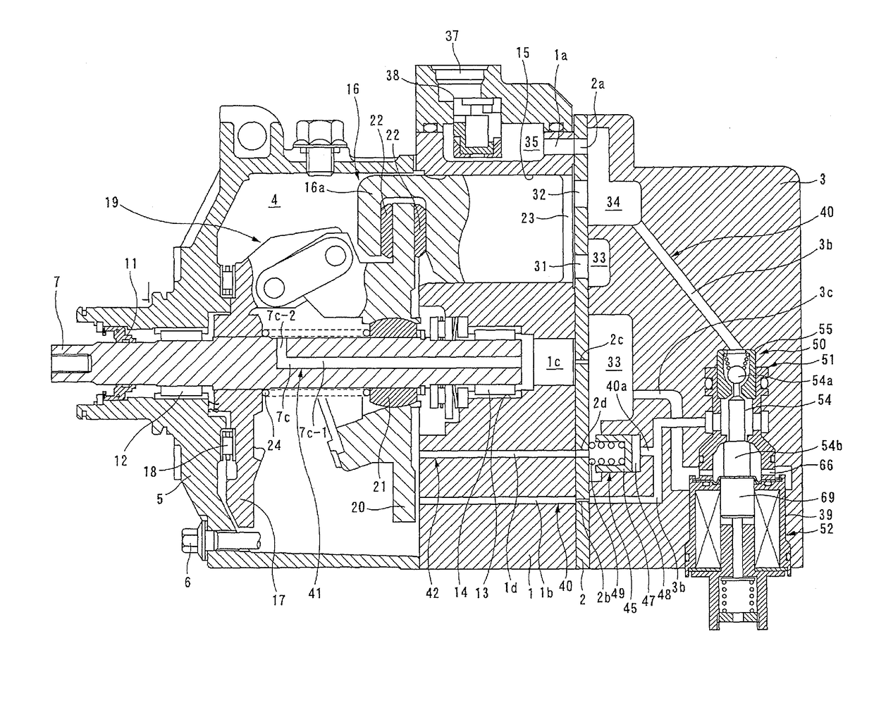
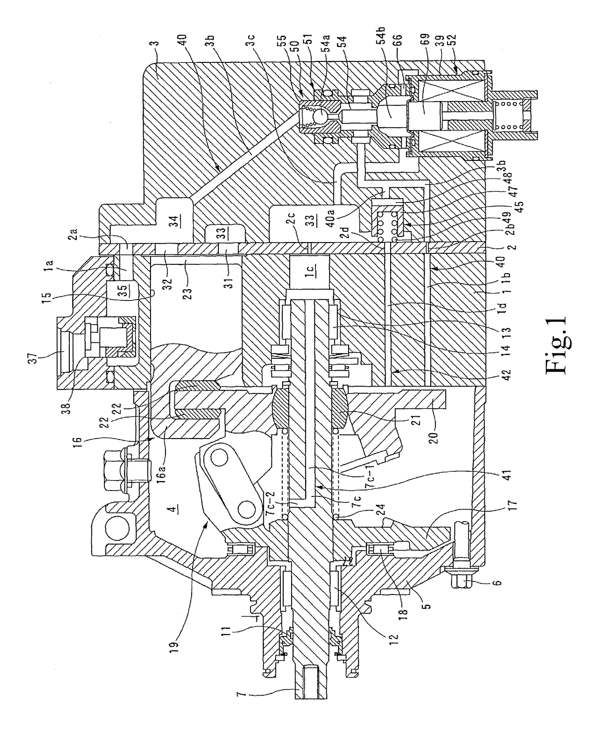
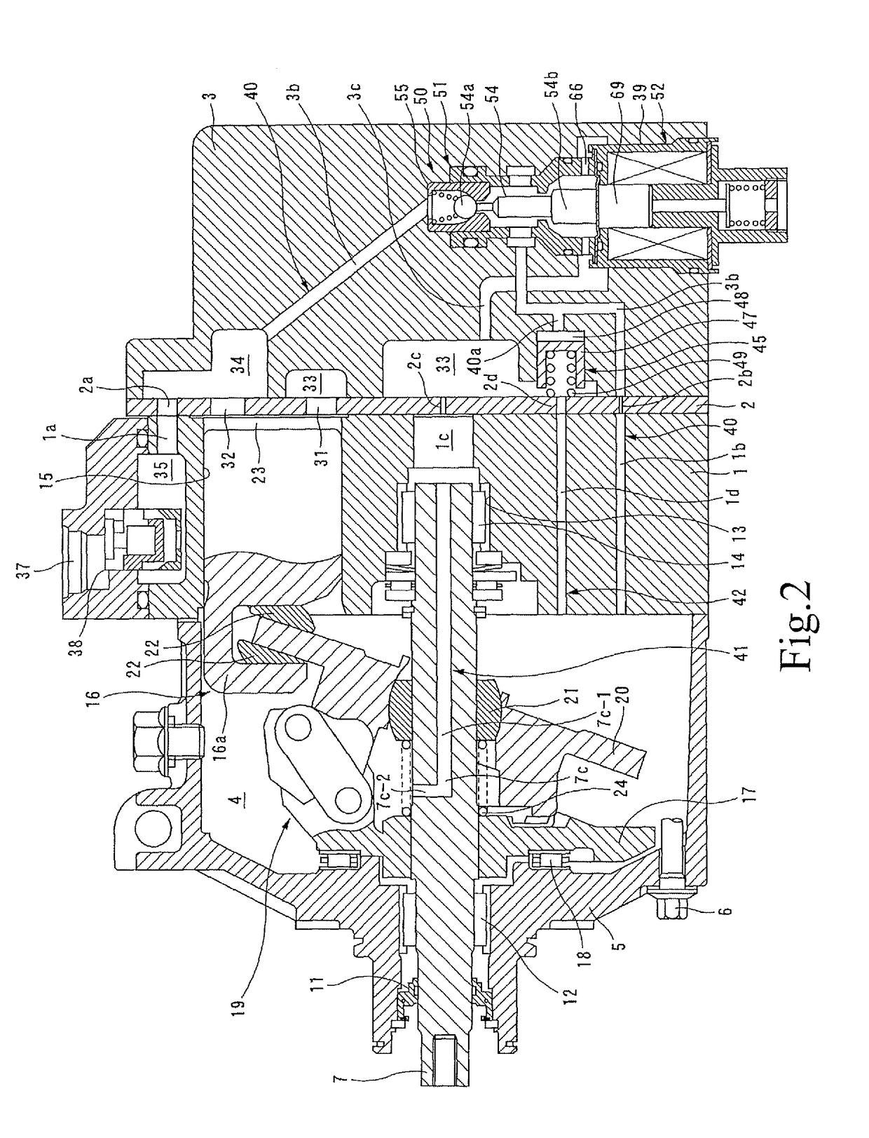
[0039]FIG. 1 to FIG. 3 illustrate a variable capacity compressor according to the present invention. The variable capacity compressor includes a cylinder block 1, a rear head 3 assembled to a rear side (right side in the drawing) of the cylinder block 1 via a valve plate 2, and a front head 5 assembled to block up a front side (left side in the drawing) of the cylinder block 1 and defining a control pressure chamber 4. The front head 5, the cylinder block 1, the valve plate 2, and the rear head 3 are fastened in an axial direction by a tightening bolt 6 to constitute a housing of the compressor.

[0040]The control pressure chamber 4 defined by the front head 5 and the cylinder block 1 houses a drive shaft 7 projecting at a front end thereof from the front head 5. A portion of the drive shaft 7 projecting from the front head 5 is provided with a drive pulley, not illustrated, to transmi...


PUM


Abstract

[Object] To provide a variable capacity compressor configured to achieve an enhancement of an activation performance of a compressor and reduce an amount of internally circulating refrigerant during an intermediate stroke in a simple structure.
[Solving Means] A supply passage 40 configured to cause a discharge chamber 34 and a control pressure chamber 4 to communicate with each other; a first bleed passage 42 configured to cause the control pressure chamber 4 and an inlet chamber 33 to communicate with each other; a first control valve 50 configured to adjust an opening degree of the supply passage 40; and a second control valve 45 provided on the first bleed passage 42 are provided, and the second control valve 45 includes: a spool 47 housed in a spool housing recess formed on a bleed passage and configured to open and close the first bleed passage 42, a back pressure chamber 48 formed behind the spool 47, and biasing means (compression spring 49) configured to bias the spool 47 in a direction of opening the first bleed passage 42. The back pressure chamber 48 of the second control valve 45 is selectively connected to the discharge chamber 34 or the inlet chamber 33 via the first control valve 50.

Description

TECHNICAL FIELD[0001]The present invention relates to a variable capacity compressor configured to vary a discharge capacity by adjusting a pressure in a control pressure chamber and, more specifically, to a variable capacity compressor including a supply passage causing a discharge chamber and a control pressure chamber to communicate with each other and a bleed passage causing the control pressure chamber and an inlet chamber to communicate with each other, and configured to adjust a pressure in the control pressure chamber by a control valve provided on the supply passage and a control valve provided on the bleed passage.BACKGROUND ART[0002]Variable capacity compressors employ a mechanism for adjusting a stroke amount of a piston by changing an angle of inclination of a swash plate by adjusting a pressure in a control pressure chamber, thereby varying a discharge capacity. Known examples of such a compressor include a compressor in which the discharge chamber and the control pres...

Claims


Application Information

Patent Timeline
IPC IPC(8): F04B27/18F04B27/08
CPCF04B27/1804F04B27/086F04B27/0839F04B1/146F04B1/295F04B2027/1822F04B2027/1827F04B2027/1831F04B2027/1872F04B2027/1881
Inventor AMEMORI, MASANORISUZUKI, KENTAROKONISHI, TAKESHIOHK, CHANGHEONENDO, TAKAYUKIKAZAHAYA, YUKIO
Owner VALEO JAPAN CO LTD
Why Eureka
Try Eureka