Unlock instant, AI-driven research and patent intelligence for your innovation.

Scanning driving circuits

Active Publication Date: 2018-07-05
WUHAN CHINA STAR OPTOELECTRONICS TECH CO LTD
View PDF0 Cites 9 Cited by
  • Summary
  • Abstract
  • Description
  • Claims
  • Application Information

AI Technical Summary

Benefits of technology

The present patent is about a circuit that reduces the power consumption and loading of clock signals in a scanning driving circuit. It uses a forward-backward scanning circuit and a pull-down circuit to perform the pull-down control to the first and second scanning lines. The circuit outputs the first and second scanning driving signals to drive corresponding pixel cells. This reduces the power consumption and loading of clock signals.

Problems solved by technology

Thus, a plurality of pull-down modules have to be configured, which may result in loading and greater power consumption of clock signals.

Method used


Image

  • Scanning driving circuits
  • Scanning driving circuits
  • Scanning driving circuits

Examples


Embodiment Construction

[0023]Embodiments of the invention will now be described more fully hereinafter with reference to the accompanying drawings, in which embodiments of the invention are shown.

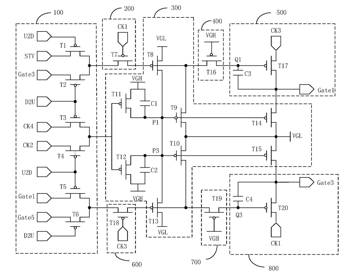
[0024]Referring to FIG. 1, the conventional flat display includes a plurality of scanning lines, and thus the scanning driving units corresponding to the scanning lines have to be configured. Each of the scanning driving units can only drive one scanning line. Each of the scanning driving units includes a forward-backward scanning circuit 10, an input circuit 20, a pull-down circuit 30, a control circuit 40, and an output circuit 50, wherein each of the scanning driving units includes a pull-down circuit for controlling a pull-down control signal point (P1), which results in greater loading and greater power consumption of the clock signals (CK2, CK4).

[0025]FIG. 2 is an operational timing diagram of one conventional scanning driving unit. When a first scanning control voltage (U2D) is at a high level and a second...


PUM


Abstract

The present disclosure relates to a scanning driving circuit including a plurality of cascaded-connected scanning driving units. Each of the scanning driving unit includes a forward-backward scanning circuit, a first and a second input circuit outputting first and second input signals; a pull-down circuit outputting first or second pull-down signals and pulling down or charging a first pull-down control signal point or a second pull-down control signal point; a first and a second control circuit charging or pulling down the first pull-down control signal point or the second pull-down control signal point; and the first and the second output circuit generating the first and the second scanning driving signals for the first and the second scanning line to drive pixel cells.

Description

BACKGROUND OF THE INVENTION1. Field of the Invention[0001]The present disclosure relates to display technology, and more particularly to a scanning driving circuit.2. Discussion of the Related Art[0002]Currently, scanning driving circuits are adopted in flat displays, that is, the manufacturing process of thin film transistors (TFT) flat displays is adopted to configure the scanning driving circuit on an array substrate to realize the driving method conducted row by row. Generally, each of the scanning driving units can only drive one scanning line, and each of the scanning driving units has to be configured with a pull-down module to control the pull-down control signal point. A plurality of scanning driving units are provided due to the plurality of scanning lines. Thus, a plurality of pull-down modules have to be configured, which may result in loading and greater power consumption of clock signals.SUMMARY[0003]The present disclosure relates to a scanning driving circuit for redu...

Claims


Application Information

Patent Timeline
IPC IPC(8): G09G3/20
CPCG09G3/2096G09G2310/0283G09G2310/067G09G3/20G09G2310/0202G09G2310/0286
Inventor ZHAO, MANG
Owner WUHAN CHINA STAR OPTOELECTRONICS TECH CO LTD