Fault diagnosis apparatus, fault diagnosis method, and fault diagnosis program

Active Publication Date: 2018-07-05
FUJIFILM CORP
View PDF0 Cites 9 Cited by
  • Summary
  • Abstract
  • Description
  • Claims
  • Application Information

AI Technical Summary

Benefits of technology

[0020]According to some aspects of the present invention, it is possible to assist an op

Problems solved by technology

In the technique disclosed in JP5039739B, however, fault information to be acquired is limited to known information.
If a sufficient amount of fault information is not accumulated or if an unknown fault occurs, a possible cause of the fault is n

Method used


Image

  • Fault diagnosis apparatus, fault diagnosis method, and fault diagnosis program
  • Fault diagnosis apparatus, fault diagnosis method, and fault diagnosis program
  • Fault diagnosis apparatus, fault diagnosis method, and fault diagnosis program

Examples


Example

First Embodiment

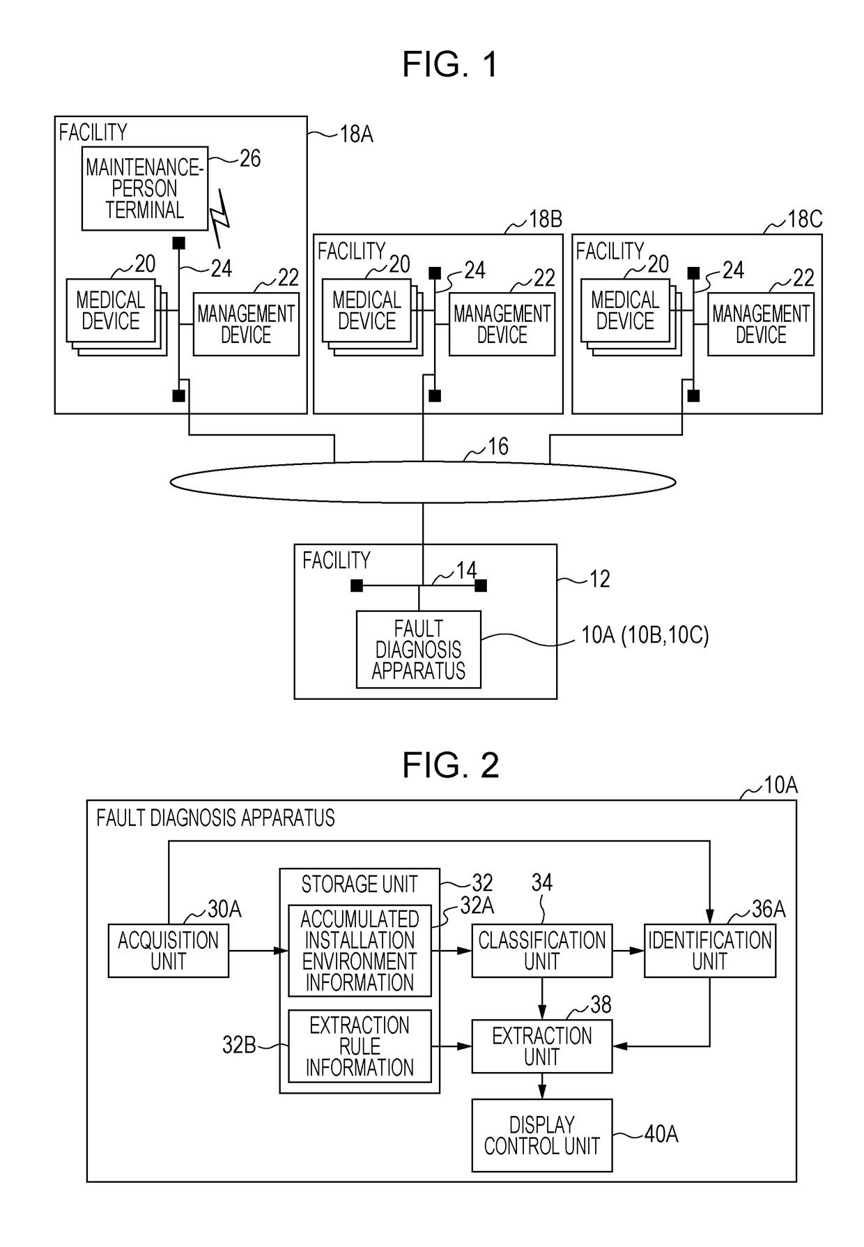
[0038]First, a connection configuration of a fault diagnosis apparatus 10A, medical devices 20, and management devices 22 according to this embodiment will be described with reference to FIG. 1. As illustrated in FIG. 1, the fault diagnosis apparatus 10A according to this embodiment is placed in a facility 12 and is connected to a network 16 such as a WAN (Wide Area Network) via a network 14 such as a LAN (Local Area Network).

[0039]Further, in each of facilities 18A to 18C, a plurality of medical devices 20 to be diagnosed by the fault diagnosis apparatus 10A and a management device 22 that manages the medical devices 20 are installed. The medical devices 20 and the management device 22 are connected to each other via a network 24 such as a LAN, and the network 24 is connected to the network 16. Thus, the medical devices 20 in the facilities 18A to 18C and the fault diagnosis apparatus 10A in the facility 12 are capable of communicating with each other via the networ...

Example

Second Embodiment

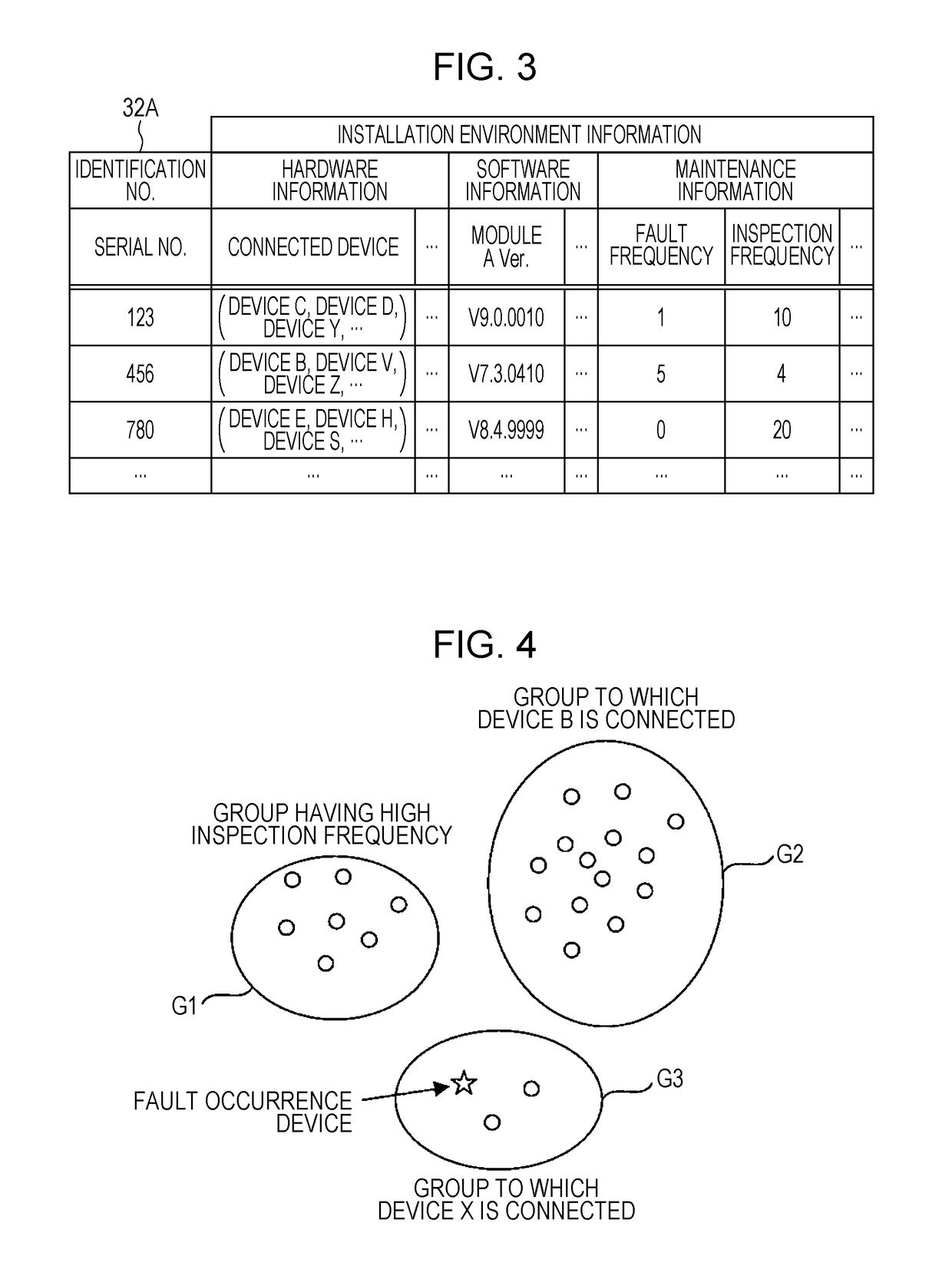
[0081]In the first embodiment, an exemplary embodiment has been described in which a process for classifying the medical devices 20 into a plurality of groups is performed when fault diagnosis is performed. In contrast, this second embodiment is different from the first embodiment in that the process for classifying the medical devices 20 into a plurality of groups is periodically performed in advance.

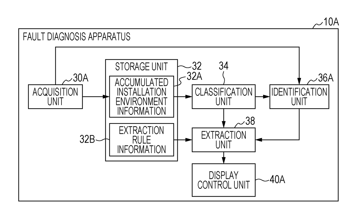
[0082]A connection configuration of a fault diagnosis apparatus 10B, medical devices 20, and management devices 22 according to this embodiment is similar to the connection configuration of the fault diagnosis apparatus 10A, the medical devices 20, and the management devices 22 according to the first embodiment (see FIG. 1) described above, and a description thereof is thus omitted here. A configuration of a main part of an electrical system of the fault diagnosis apparatus 10B according to this embodiment is also similar to the configuration of the main part of the el...

Example

Third Embodiment

[0094]In this third embodiment, an exemplary embodiment will be described in which fault information concerning the types of faults that have previously occurred in the medical devices 20 is also used in the first embodiment described above. A connection configuration of a fault diagnosis apparatus 10C, medical devices 20, and management devices 22 according to this embodiment is similar to the connection configuration of the fault diagnosis apparatus 10A, the medical devices 20, and the management devices 22 according to the first embodiment (see FIG. 1) described above, and a description thereof is thus omitted here. A configuration of a main part of an electrical system of the fault diagnosis apparatus 10C according to this embodiment is also similar to the configuration of the main part of the electrical system of the fault diagnosis apparatus 10A according to the first embodiment (see FIG. 5) described above, and a description thereof is thus omitted here.

[0095]...


PUM


Abstract

A fault diagnosis apparatus acquires, by using an acquisition unit, for each of a plurality of medical devices, installation environment information including a plurality of items about an installation environment in which each of the plurality of medical devices is installed; classifies, by using a classification unit, the plurality of medical devices into a plurality of groups on the basis of the installation environment information; extracts, by using an extraction unit, an item in the installation environment information representing a feature of a group to which a device in which a fault has occurred among the plurality of medical devices belongs, the feature being different from that of the other groups; and performs control, by using a display control unit, to cause a display unit to display an extraction result obtained by the extraction unit.

Description

CROSS-REFERENCE TO RELATED APPLICATIONS[0001]This application is a Continuation of PCT International Application No. PCT / JP2016 / 073625 filed on Aug. 10, 2016, which claims priority under 35 U.S.C § 119(a) to Japanese Patent Application No. 2015-187381 filed on Sep. 24, 2015. Each of the above application(s) is hereby expressly incorporated by reference, in its entirety, into the present application.BACKGROUND OF THE INVENTION1. Field of the Invention[0002]The present invention relates to a fault diagnosis apparatus, a fault diagnosis method, and a non-transitory computer readable recording medium storing a fault diagnosis program.2. Description of the Related Art[0003]In the related art, there are known techniques related to location of causes of faults in devices such as electronic devices and techniques for detecting signs of the faults. As a technique of this type, JP5039739B discloses a fault position examination device that locates the position of a fault that has occurred in a...

Claims


Application Information

Patent Timeline
IPC IPC(8): G16H40/40G05B23/02
CPCG16H40/40G05B23/02G05B23/0267G05B2219/32287
Inventor TAKEI, MIZUKI
Owner FUJIFILM CORP
Why Eureka
Try Eureka