Imaging arrangement

a technology of image arrangement and optical bandwidth, applied in the field of image arrangement, can solve the problems of difficult correlation of thermal image of a scene with its optical equivalent, and the limitations of conventional viewing systems of this kind

Inactive Publication Date: 2011-11-22
GEC MARCONI +1
View PDF16 Cites 10 Cited by
  • Summary
  • Abstract
  • Description
  • Claims
  • Application Information

AI Technical Summary

Benefits of technology

[0006]The reflected laser light which is returned from the scene is separated from the emitted thermal radiation by means of a narrow band filter. In this way the effect of ambient illumination of the scene by other sources of light, including daylight, can be removed if desired. The use of laser light to illuminate the scene in a scanned fashion enables various kinds of data to be obtained for the individual pixels in the scene: for example, the range and line-of-sight velocity for objects in the scene. This data can be correlated with a conventional image derived from reflected light representing tone values to assist in the identification of moving objects, and all of the optical data can be directly correlated with the infrared data as it is obtained via the common scanning device. Furthermore, since the optical part of system makes use of the scanning device, the overall arrangement can be compact, and permits the optical data to be considered on a pixel-by-pixel basis which is made possible by the use of the two-dimensional scanning raster pattern.

Problems solved by technology

Conventional viewing systems of this kind tend to be restricted as to the optical bandwidth to which they are sensitive, and in particular they are generally insensitive to infrared (thermal) radiation.
It is, however, difficult to correlate such a thermal image of a scene with its optical equivalent, in which the optical images result from light reflected by the viewed scene.

Method used


Image

  • Imaging arrangement
  • Imaging arrangement
  • Imaging arrangement

Examples


Embodiment Construction

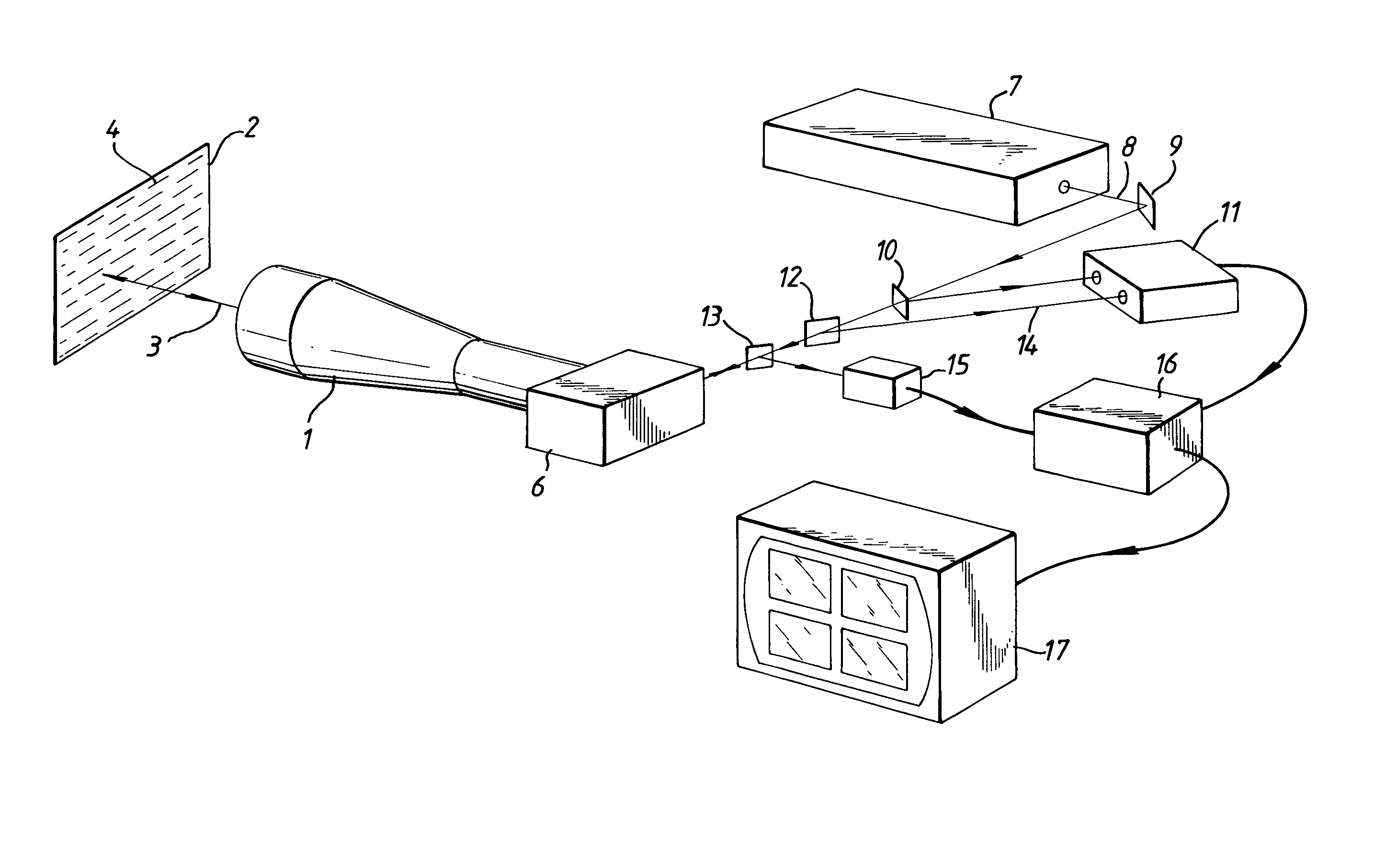
[0011]Referring to FIG. 1 there is shown therein a telescope 1 by means of which light from the imaging arrangement can be directed upon a field of view. This field of view 2 is represented very diagramatically by the rectangle and the beam of light 3 is arranged to scan across each point in this field of view systematically in a television-like raster pattern consisting of a number of parallel line scans 4. Because of the nature of the scanner 6 which generates this pattern, the time intervals between adjacent line scans are extremely short. The light used to scan the scene is a very narrow laser beam consisting essentially of monochromatic light, having a very small frequency modulation bandwidth superimposed thereon.

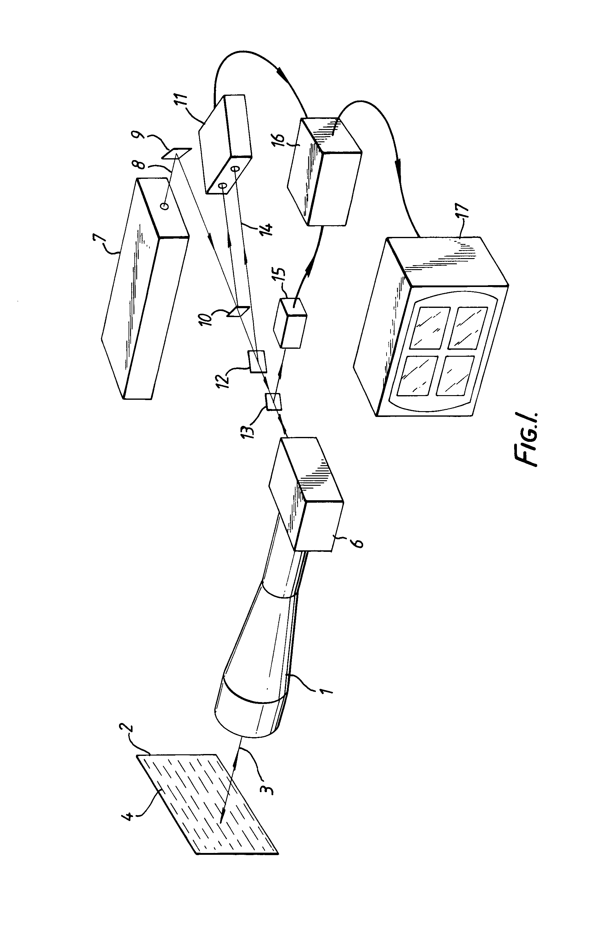
[0012]The scanner 6 is operative in a known manner in order to trace out the raster pattern 4, and its details will be described subsequently with reference to FIG. 2. The laser beam originates with a laser source 7 which produces a narrow output beam 8 which is refle...


PUM


Abstract

An imaging arrangement combines a thermal imager with a laser imager to enable several correlated pictures to be produced which show different properties of the same field of view. A common scanning device is used to scan each pixel in the field of view in a raster-like pattern, and for each pixel data can be derived representing thermal content, range, optical reflectivity and velocity. The last three properties are obtained by coupling an optical interferometer to the scanning device which generates the picture representing the thermal content.

Description

BACKGROUND OF THE INVENTION[0001]This invention relates to an imaging arrangement. It is well known to produce two-dimensional images of a viewed scene, for example by means of a television camera or the like. Conventional viewing systems of this kind tend to be restricted as to the optical bandwidth to which they are sensitive, and in particular they are generally insensitive to infrared (thermal) radiation. Various kinds of thermal imaging systems are well known, and include specially adapted television-like cameras having a shutter in front of a heat sensitive image surface which responds to the changes in temperature, resulting from shutter action. An alternative kind of thermal imaging system of higher resolution involves the use of a scanning arrangement which causes each part of a scene to be viewed in turn by a small very sensitive sensor or array of sensors. It is, however, difficult to correlate such a thermal image of a scene with its optical equivalent, in which the opti...

Claims


Application Information

Patent Timeline
Patent Type & Authority Patents(United States)
IPC IPC(8): G02B26/10H04N3/09
CPCH04N3/09H04N23/11
Inventor YOUNGS, ERIC GEOFFREY DUNLOPCOX, RAYMOND SAMUELBLACKMORE, KEVIN DARYL
Owner GEC MARCONI
Why Eureka
Try Eureka