Apparatus and method for tracing activities of a shader program executed on shader circuitry of a data processing apparatus

a data processing apparatus and shader circuit technology, applied in the direction of program control, image data processing, specific program execution arrangements, etc., can solve the problems of inability to debug fragment shader programs, and inability to detect shader programs

Inactive Publication Date: 2012-04-17
ARM LTD
View PDF11 Cites 10 Cited by
  • Summary
  • Abstract
  • Description
  • Claims
  • Application Information

AI Technical Summary

Benefits of technology

[0014]Since the trace vector is constrained to be of the same size as the colour value, then this allows the image buffer to be reused for storing the trace vector data during the trace mode of operation, thereby eliminating the need for any additional dedicated trace buffer to be provided. By producing trace vectors containing a plurality of items of execution path information indicative of the execution path taken for particular input data, this enables the user of the trace vector information to understand which parts of the shader program are used for particular arrangements of input data. Hence, considering the earlier discussed fragment shader optimisation issue, the invention allows, via the trace vectors, access to per-pixel execution path data for a variety of rendered frames, allowing a programmer to visualise the execution time of a fragment shader, thereby allowing the programmer to identify potential performance problems, and to hence modify the code with the aim of seeking to alleviate those performance problems.
[0015]Similarly, considering the issue of code coverage measurement, the present invention can be used to obtain execution path data for every pixel in every visible polygon of a scene, and hence will assist the user in identifying areas of the fragment shader code that have not been executed, thus allowing the user to modify the test sequences so as to seek to utilise such unused shader code portions.
[0016]Similarly, considering the fragment shader debugging issue discussed earlier, the present invention can provide, via the trace vectors, an indication of the execution path utilised for every pixel in a sequence of frames, thereby making it easier to identify the sections of code that cause a bug to occur, thereby decreasing the time required to identify and fix the bug.
[0018]It has been found that the present invention provides a particularly efficient mechanism for obtaining information about the execution path taken through a shader program for different sets of input data, and this information can assist in significantly improving the speed of testing shader programs, for example being particularly useful in the areas of fragment shader optimisation, code coverage measurement and fragment shader debugging.
[0022]Alternatively, or in addition, said plurality of items of execution path information comprise one or more loop count items, each loop count item identifying a number of times a corresponding loop within the shader program was repeated. By keeping track of the number of times a loop is repeated, this avoids the need to keep separate items of execution path information for each iteration through that loop, and therefore can provide a more efficient mechanism for providing execution path information in such instances.
[0029]The shader circuitry can be arranged in a variety of ways. However, in one embodiment, the shader circuitry has multiple execution pipelines, such that multiple instances of the shader program are executed in parallel, each instance of the shader program operating on input data for different pixels. Hence, when in the trace mode of operation, multiple separate trace vectors can be produced in parallel using the input data for a number of different pixels so as to produce in parallel execution path information indicative of the execution path taken by the shader program when processing those different sets of input data. Hence, such execution path data can be rapidly produced for multiple different sets of input data.

Problems solved by technology

Firstly, considering fragment shader optimisation, the time required to execute a fragment shader program is critical to maintaining a smooth 3D graphical experience, but the complexity of scenes, and thus shaders, can vary greatly.
Considering the issue of fragment shader debugging, the varying nature of 3D scenes makes debugging fragment shader programs difficult.
Since the process described in the above article requires single stepping through the lines of code making up the fragment shader, it is inherently a very invasive debugging technique.
Further, the described process is very labour intensive, since to understand how the input data for any particular pixel of interest is processed by the shader program, it is necessary to perform the single stepping process multiple times for multiple different lines of code in order to determine the intermediate values of selected variables at each of those lines of code.
Furthermore, because of the invasive nature of the single stepping operation, it cannot be guaranteed that the code is operating in exactly the same way as it would if execution were not halted between each line of code.
As with the earlier article, the technique described in this paper is very labour intensive and invasive, and would require multiple runs through the process to establish information about how the input data for any particular pixel of interest is processed by the shader program.

Method used


Image

  • Apparatus and method for tracing activities of a shader program executed on shader circuitry of a data processing apparatus
  • Apparatus and method for tracing activities of a shader program executed on shader circuitry of a data processing apparatus
  • Apparatus and method for tracing activities of a shader program executed on shader circuitry of a data processing apparatus

Examples


Embodiment Construction

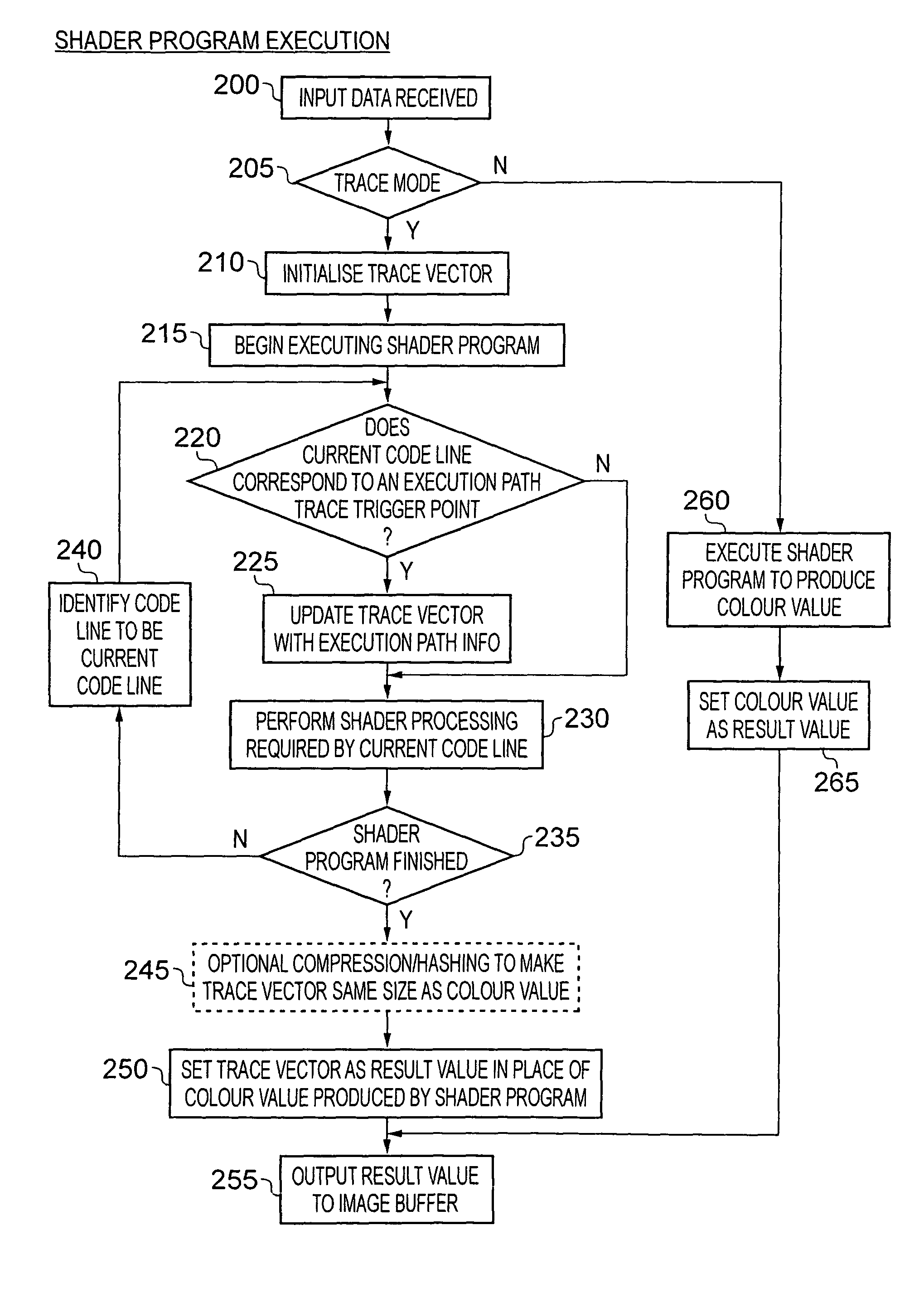
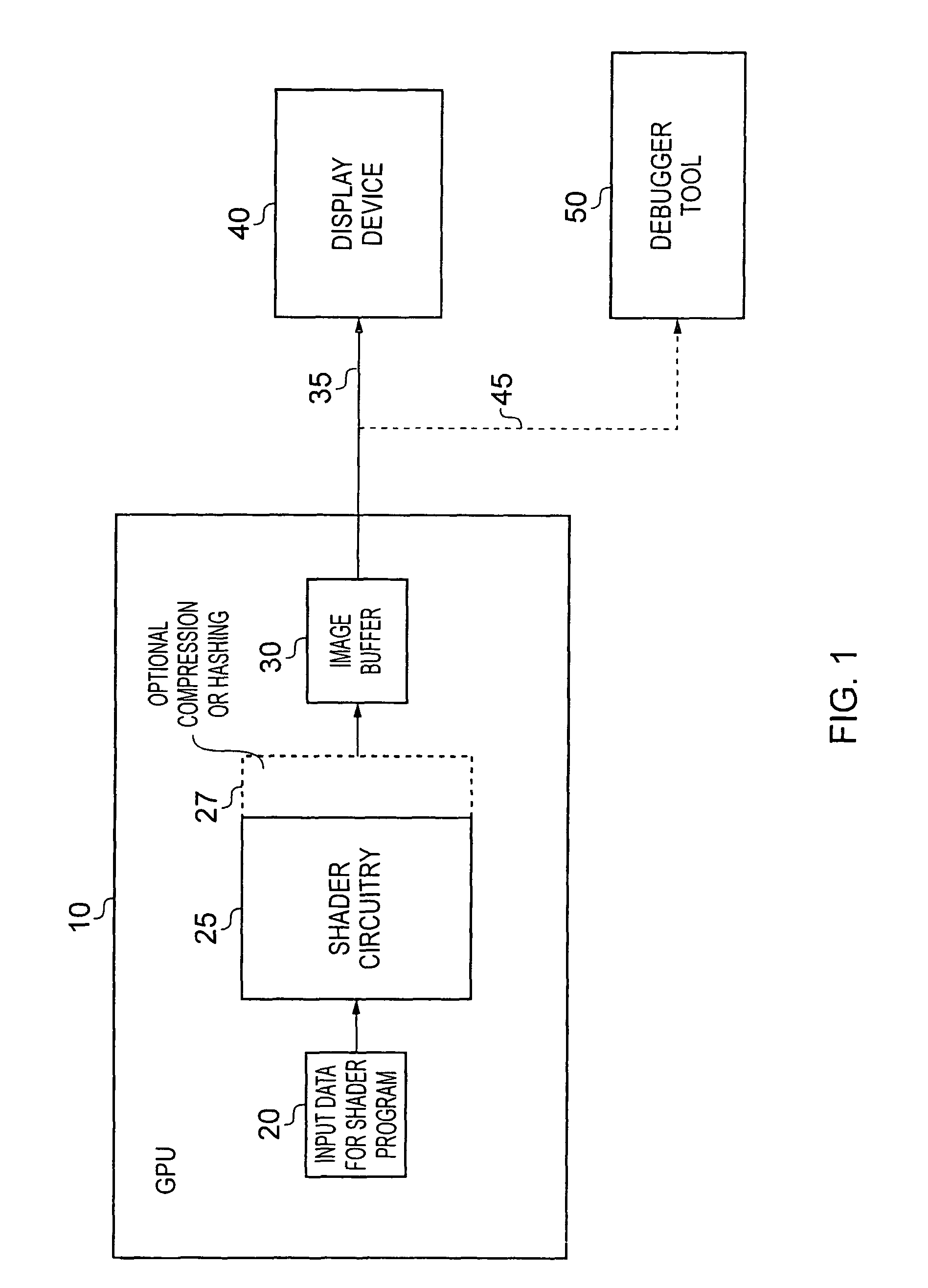
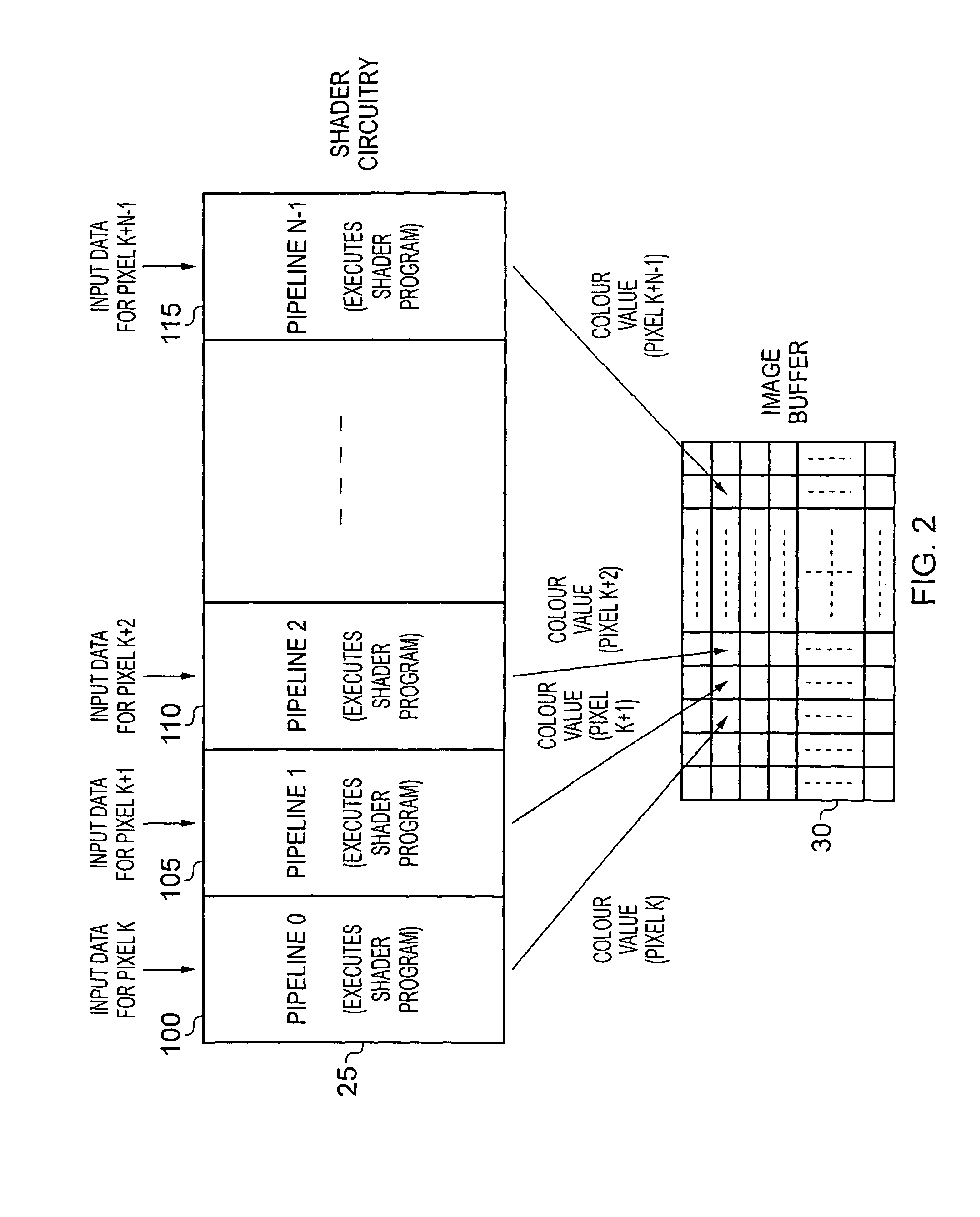
[0046]FIG. 1 is a block diagram of a data processing system in which a data processing apparatus of embodiments of the present invention may be provided. In this example, the data processing apparatus takes the form of a GPU 10 in which shader circuitry 25 is provided. Input data 20 is provided for supply to the shader circuitry 25, that input data having been produced using any of a number of standard processing steps on image data required to be displayed on screen. In particular, as is well-known to those skilled in the art, a display screen is typically divided into a number of polygons with attributes being associated with each vertex of the polygon. In addition, parameter values shared across an entire display scene, often referred to as “uniforms”, may also be specified. A rasterizer circuit will then typically determine all of the pixels that are required to form each polygon. For a pixel within a particular polygon, the input attribute data for that pixel is typically deriv...


PUM


Abstract

A data processing apparatus and method are provided for tracing activities of a shader program executed on shader circuitry of a data processing apparatus. The data processing apparatus comprises shader circuitry which is responsive to input data for a pixel to execute a shader program to generate a color value for the pixel. The shader program has multiple execution paths via which the color value may be generated, and which execution path is taken is dependent on the input data. An image buffer having a plurality of storage locations is provided, with each storage location being used to store the color value generated by the shader circuitry for an associated pixel. In a trace mode of operation, execution of the shader program by the shader circuitry causes a trace vector to be generated containing a plurality of items of execution path information indicative of the execution path taken, the trace vector comprising a plurality of fields, each field being used to store one item of execution path information. The trace vector as output is constrained to be of the same size as the color value, and in the trace mode of operation the trace vector is stored in one of the storage locations of the image buffer in place of the color value generated by the shader program. This has been found to provide an efficient mechanism for obtaining execution path data useful when performing a variety of debugging activities in respect of a shader program.

Description

FIELD OF THE INVENTION[0001]The present invention relates to an apparatus and method for tracing activities of a shader program executed on shader circuitry of a data processing apparatus.BACKGROUND OF THE INVENTION[0002]In modern 3D graphics systems, for each pixel within a polygon, it is possible to execute a program called a fragment shader (also referred to as a pixel shader). The fragment shader is used to determine the colour of a pixel based on input data related to that pixel and decisions made during the execution of the fragment shader code.[0003]When developing a fragment shader program, it is important to be able to thoroughly test the operation of the fragment shader program in order to ensure it will operate as intended. Various issues are relevant when seeking to test the operation of a fragment shader program. Firstly, considering fragment shader optimisation, the time required to execute a fragment shader program is critical to maintaining a smooth 3D graphical expe...

Claims


Application Information

Patent Timeline
Patent Type & Authority Patents(United States)
IPC IPC(8): G06T15/50G06T1/60G06F9/44G06T15/00
CPCG06F11/3636G06T15/005
Inventor CAPEWELL, MARTYNBUTCHER, DAVID JOHNCATHERALL, ROBERT JAMESHORSMAN, PETER JAMES
Owner ARM LTD
Why Eureka
Try Eureka