
Encapsulating bag for pressurized cylinders to reduce particulate contamination for clean room use

Inactive Publication Date: 2008-02-28
PALT NEIL
View PDF41 Cites 10 Cited by
  • Summary
  • Abstract
  • Description
  • Claims
  • Application Information

AI Technical Summary

Benefits of technology

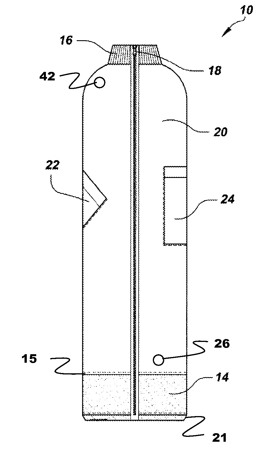
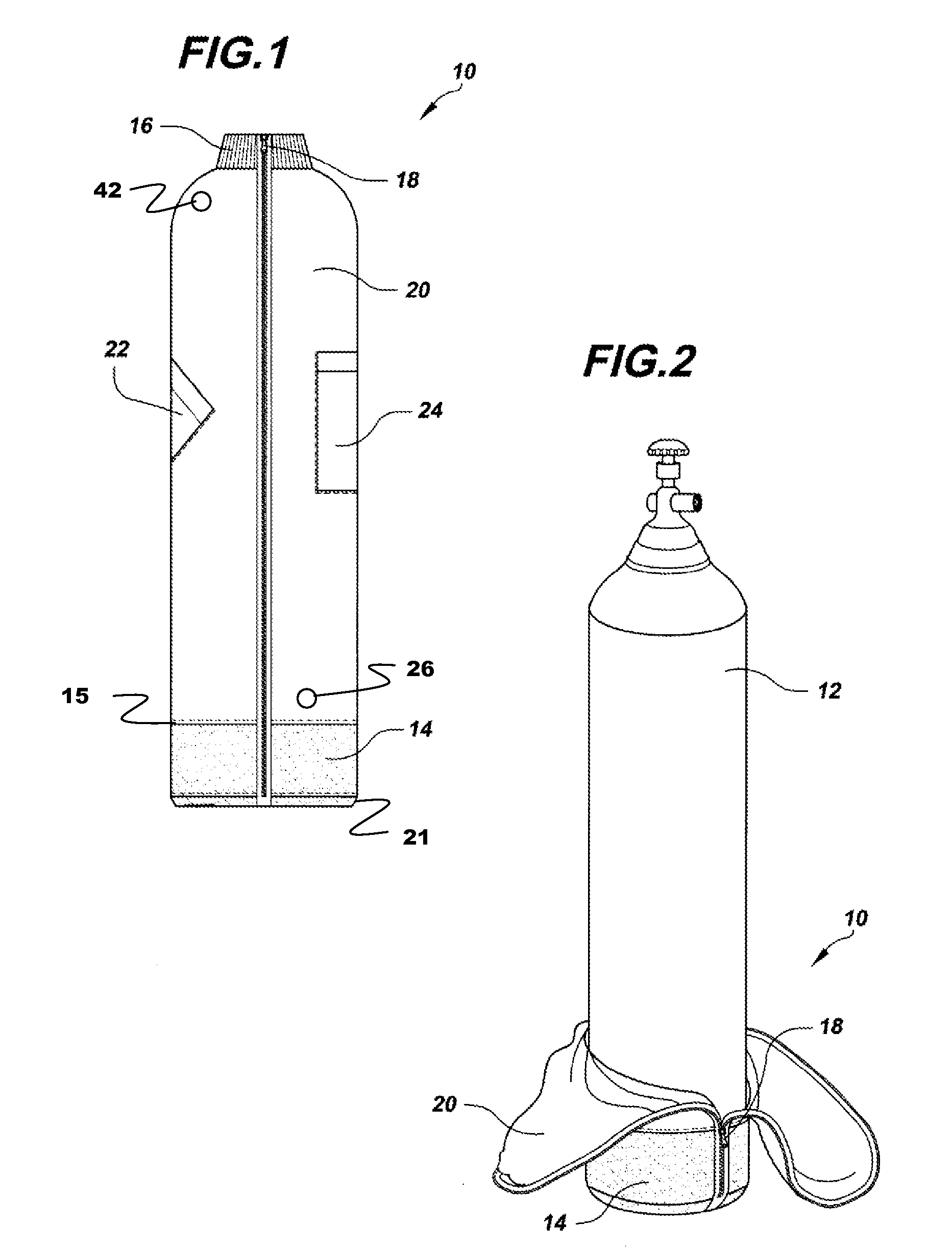
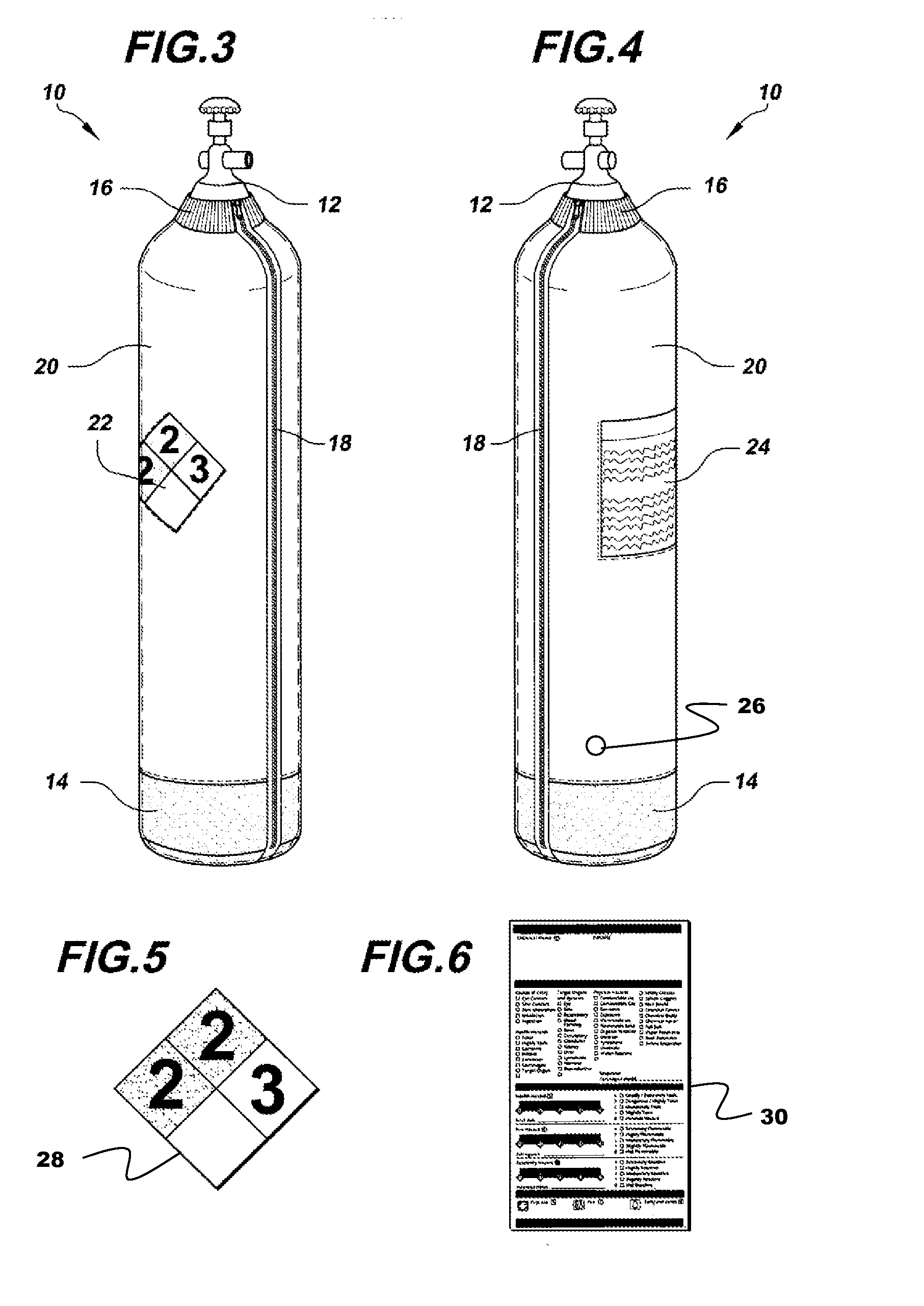
[0006]The present invention provides particulate containment for gas cylinders through the use of an encapsulating bag having a main body of fabric such as polyester or flouropolymer having a weave sufficiently tight to preclude cylinder contaminant transmission. A bottom boot engages a lower portion of the main body to cover the bottom of the cylinder. A separation closure means such as a non-metal zipper is incorporated into the main body for opening the main body for insertion of the cylinder. A cuff of clean room approved material is attached to a top circumference of the bag main body for close engagement of a top boss of the cylinder to preclude contaminant escape. An ESD button is incorporated in the body of the bag for attachment of a conducting lead for grounding connection. Color selection for the bag body is employed in alternative embodiments to assist in identification of the cylinder type enclosed within the bag.
[0008]Fitted pouches of transparent clean room approved materials attached to the bag body allow display of hazardous material identification placards and material safety data sheets for the contents of the cylinders enclosed in the bag. Use of a fabric enclosure provided by the invention for gas cylinders allows laundering and repetitive use while maintaining a presentable appearance.

Problems solved by technology

The combination of cylinder mass and pressure cycling and release makes the cylinders subject to condensation issues with associated corrosion and contamination as well as chipping or cracking of the paint or other coatings on the cylinders.
Particularly where these cylinders are in use in clean room applications, such as in the semiconductor manufacturing industry, contamination caused by particulates shed from these cylinders can be of concern.

Method used


Image

  • Encapsulating bag for pressurized cylinders to reduce particulate contamination for clean room use
  • Encapsulating bag for pressurized cylinders to reduce particulate contamination for clean room use
  • Encapsulating bag for pressurized cylinders to reduce particulate contamination for clean room use

Examples


Embodiment Construction

[0017]The present invention provides a light weight cover in the form of a bag assembly 10 for a gas cylinder 12 such as process gas cylinders employed in a clean room environment for the semiconductor industry. The invention provides protection for the clean room area from particulate contamination from the surface of the cylinder due to chipping or shedding of paint or other coating on the gas cylinder. The bag assembly includes a main body 20 constructed of non-particulating material that breaths to prevent condensation on the encapsulated cylinder. Fabric for the main body is a tight weave preventing egress of particulates through the fabric. Various embodiments of the invention employ Flouropolymer or polyester fabrics having porosities of approximately 4.0 CFM air transmission or less. Polytetraflouroethylene fabric such as Gore-Tex® has been demonstrated in exemplary embodiments of the invention. In certain embodiments, a B-FORE™ polyester material is employed. The main body ...


PUM

PropertyMeasurementUnit
Electrical conductivityaaaaaaaaaa
Metallic bondaaaaaaaaaa
Transparencyaaaaaaaaaa

Abstract

An encapsulating bag for contamination control on gas cylinders employs a main body of fabric such as polyester or flouropolymer having a weave sufficiently tight to preclude contaminant transmission. A bottom boot engages a lower portion of the main body to cover the bottom of the cylinder. A separation closure means such as a non-metal zipper is incorporated into the main body for opening the main body for insertion of the cylinder. A cuff is attached to a top circumference of the bag main body for close engagement of a top boss of the cylinder to preclude contaminant escape. An ESD button is incorporated in the body of the bag for attachment of a conducting lead for grounding connection.

Description

BACKGROUND OF THE INVENTION[0001]1. Field of the Invention[0002]This invention relates generally to the field of clean room processing and, more particularly, to a bag enclosure for containing particulate contamination from gas cylinders during clean room use and general pressure cylinder protection and identification.[0003]2. Description of the Related Art[0004]Gas cylinders are employed in numerous applications. While the applications disclosed herein are directed to clean room usage of such cylinders, other applicable usage can range from home use propane bottles to very high pressure gas applications for welding or other manufacturing and health care uses. The combination of cylinder mass and pressure cycling and release makes the cylinders subject to condensation issues with associated corrosion and contamination as well as chipping or cracking of the paint or other coatings on the cylinders. Particularly where these cylinders are in use in clean room applications, such as in t...

Claims


Application Information

Patent Timeline
IPC IPC(8): B65D33/00B65D30/22B65D33/16B65D33/04B65D30/04B65D30/10
CPCF17C13/084F17C2205/0115F17C2205/0308F17C2260/044F17C2201/0109F17C2270/05F17C2201/032F17C2201/058F17C2205/052F17C2270/02F17C2201/0119
Inventor PALT, NEIL
Owner PALT NEIL
Learn More