Method for assembling conductive particles into conductive pathways and sensors thus formed

Active Publication Date: 2013-12-05
CONDALIGN AS
View PDF5 Cites 71 Cited by
  • Summary
  • Abstract
  • Description
  • Claims
  • Application Information

AI Technical Summary

Benefits of technology

[0057]Aligned single strings of CB in polymer as well as polymer composites containing CB strings can mimic the piezorestistive properties of carbon nanotubes (CNTs) and the polymer composites containing CNTs, but CB particles provide additional benefits including significantly easier mixing and lower production costs.
[0058]Aligned strings make an initially insulating composite conductive and the stretching of strings result in a piezoresistive effect due to the induced displacement of the articles. The str

Problems solved by technology

As the human body is a conductor, touching the surface of the screen results in a distortion of the screen's electrostatic field, measurable as a change in capacitance.
Problems with the current technolo

Method used


Image

  • Method for assembling conductive particles into conductive pathways and sensors thus formed
  • Method for assembling conductive particles into conductive pathways and sensors thus formed
  • Method for assembling conductive particles into conductive pathways and sensors thus formed

Examples


example 1

[0155]This example concerns the applicability of the alignment method, the use of alignment for formation of individual aligned chains in the predetermined positions.

[0156]The employed conductive particles were carbon black (CB) from Alfa Aesar, carbon nano cones CNC from n-Tec AS (Norway) and iron oxide (FeO.Fe2O3) from Sigma-Aldrich.

[0157]The employed polymer matrix was a two component low viscosity adhesive formed by combining Araldite AY 105-1 (Huntsman Advanced Materials GmbH) with low viscosity epoxy resin with Ren HY 5160 (Vantico AG).

[0158]The conductive particles were mixed in the adhesive by stirring for 30 minutes. Due to the high viscosity of mixture, efficient mixing is possible only up to 20 vol-%. of particles.

[0159]Estimated percolation threshold of these materials are at ˜2 vol-%. The mixtures are conductive above and insulators below this threshold. Particle loads of 1 / 10 of the estimated percolation threshold were used.

[0160]The particles in the matrix were aligne...

example 2

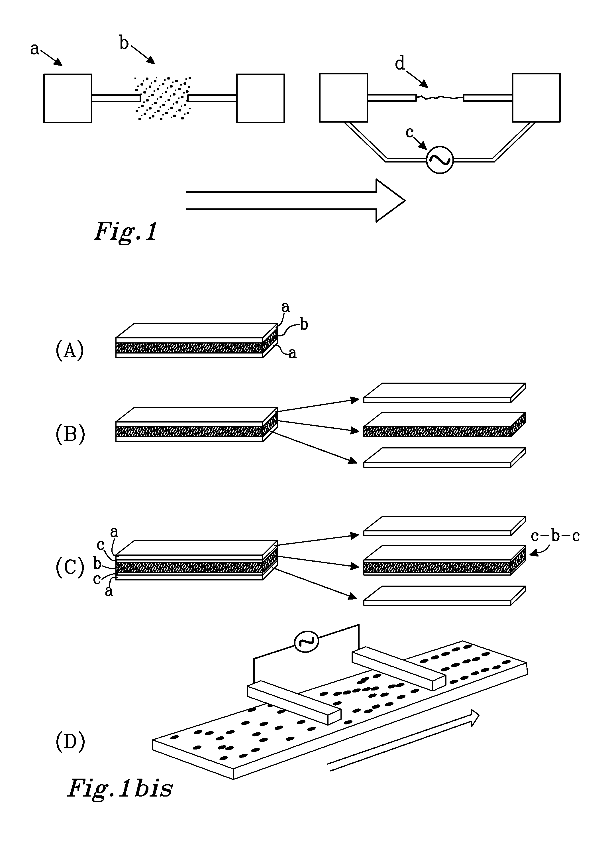
[0164]In FIG. 1b is shown removal of electrodes after alignment and thus freestanding aligned film even in the case where the matrix is adhesive. The alignment also occurs if the electrodes do not touch the material and so the alignment can be performed from the distance. When the material and electrodes are moved, continuous or stepwise, with respect to each other during the alignment, this allows continuous alignment processing and different geometries. Three possible options for the alignment settings are illustrated in FIG. 1b that shows aligned film with (A-B) and without (C-D) electrical contacts between electrodes (a) and material (b). In the case (A) the aligned film forms permanent connection between the electrodes. In the case (B) the electrodes and material are only loosely joined together and can be moved apart after alignment. In the case (C) there are insulating layers (c) between the material and electrodes and they are easily moved apart after the alignment even in t...

example 3

[0166]This example concerns the applicability of the alignment method, the use of alignment for formation of individual aligned chains in the predetermined positions.

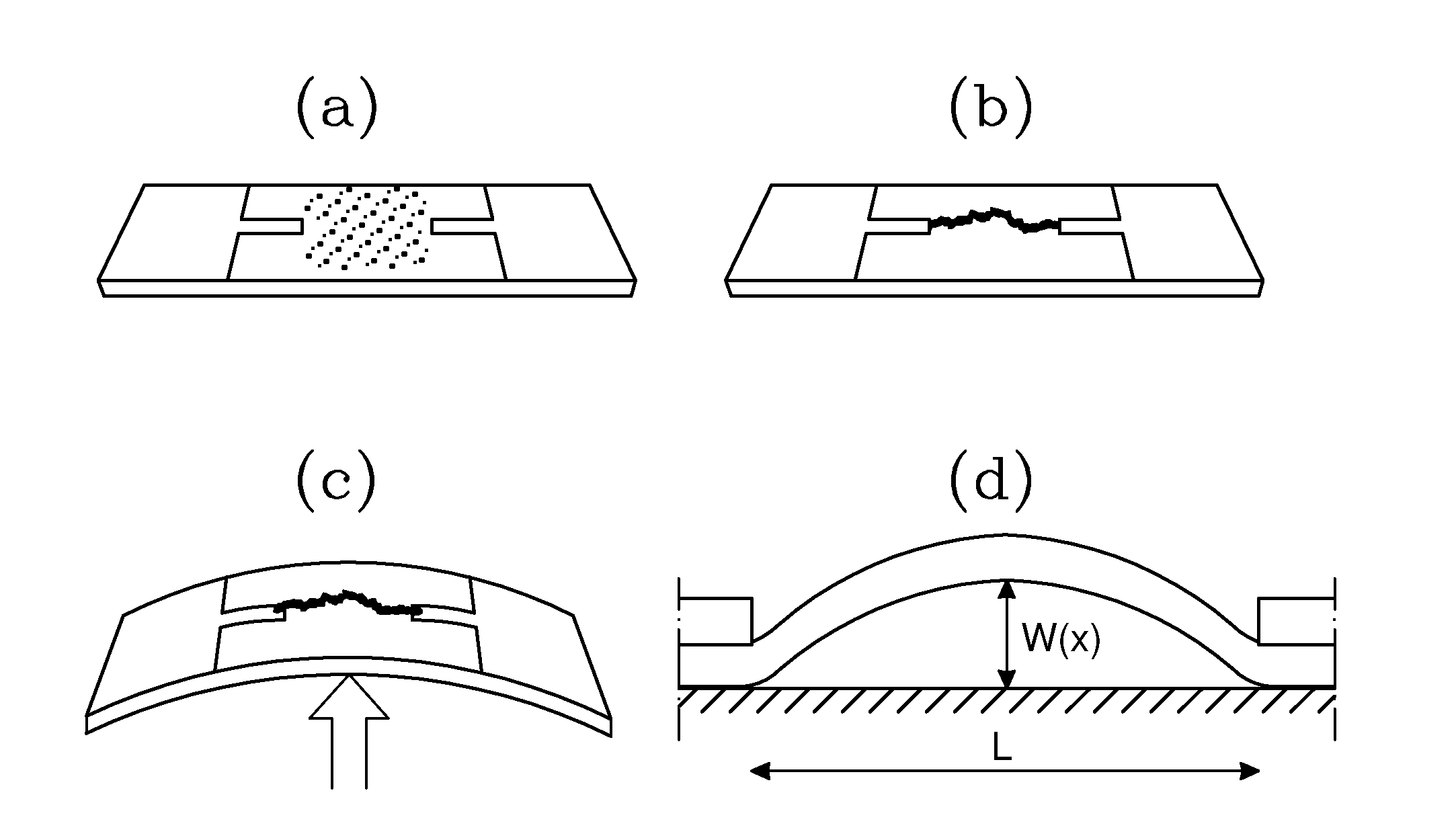
[0167]The procedure was otherwise similar to that in Example 1 but instead of generic surface the particle chain is aligned on the AFM cantilever. When the cantilever is bending, influenced due to the changing surface forces, the aligned pathway gets microscopically stretched and the particles become disconnected from each other. This influences the conductivity through the particle chain. This allows the use of aligned chain as a sensor of surface properties of the surface studied by the cantilever. This setting is illustrated in FIG. 3, where the upper image to the right illustrates a connected path, and the lower image (bent state) illustrates a disconnected path.


PUM

PropertyMeasurementUnit
Electric fieldaaaaaaaaaa
Temperatureaaaaaaaaaa

Abstract

A sensor is achieved by applying a layer of a mixture that contains polymer and conductive particles over a substrate or first surface, when the mixture has a first viscosity that allows the conductive particles to rearrange within the material. An electric field is applied over the layer, so that a number of the conductive particles are assembled into one or more chain-like conductive pathways with the field and thereafter the viscosity of the layer is changed to a second, higher viscosity, in order to mechanically stabilise the material. The conductivity of the pathway is highly sensitive to the deformations and it can therefore act as deformation sensor. The pathways can be transparent and is thus suited for conductive and resistive touch screens. Other sensors such as strain gauge and vapour sensor can also be achieved.

Description

TECHNICAL FIELD[0001]The invention concerns a method for forming a well-defined micrometer scale conductive wire or pathway comprising conductive particles on a generic substrate using an electric field. The pathway can be covered by non-conductive organic material like polymer. The pathway connects its ending points electrically, but the strength of this connection can vary with the substrate deformations, the pathway thus acting as a deformation sensor as the conductance and admittance change. The pathway structure is more sensitive to the deformations compared to the randomly oriented mesh. Pathways may also act as a capacitive sensor, and the features can be combined in a hybrid sensor. Such sensors can be used in different areas including nanomechanical cantilever sensors, cantilever sensors and touchscreens.BACKGROUND OF THE INVENTION[0002]Electrically conductive organic material containing materials can be based on the mixture of polymer-containing matrix and conductive parti...

Claims


Application Information

Patent Timeline
IPC IPC(8): B81C1/00B81B3/00
CPCB81C1/0015B81B3/0018G01N29/022G06F3/045G06F2203/04103G01N2291/0251G01N2291/0255G01N2291/0256G06F3/0443G01N2291/0427B81B2201/0221B81B2201/0207B81B2201/02B81B2201/0214
Inventor BUCHANAN, MARKKNAAPILA, MATTIHELGESEN, GEIRHOEYER, HENRIK
Owner CONDALIGN AS
Why Eureka
Try Eureka