
Display Unit with Built-in Shelving Supports

Active Publication Date: 2018-07-12
INNERWORKINGS
View PDF118 Cites 0 Cited by
  • Summary
  • Abstract
  • Description
  • Claims
  • Application Information

AI Technical Summary

Benefits of technology

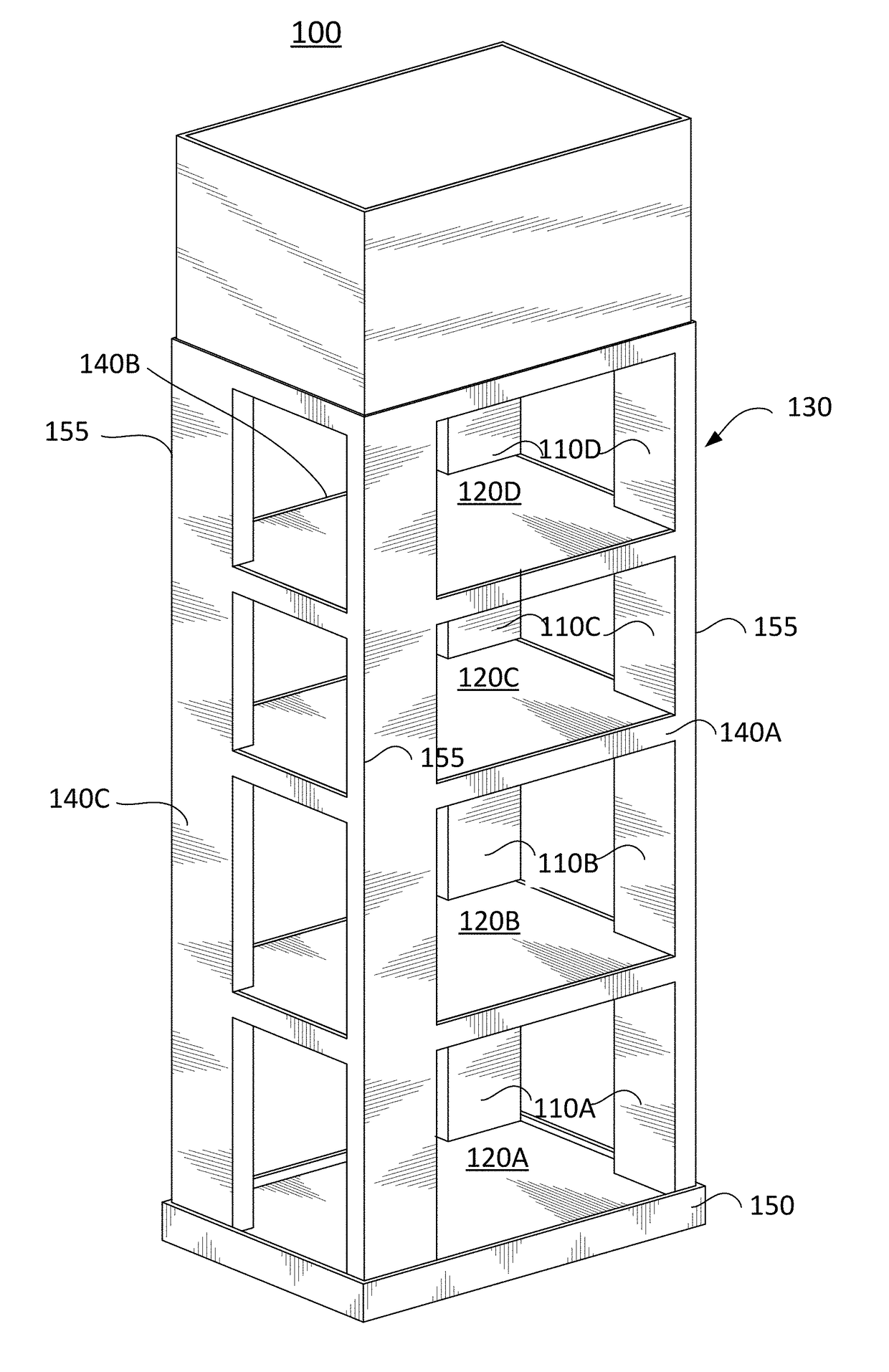
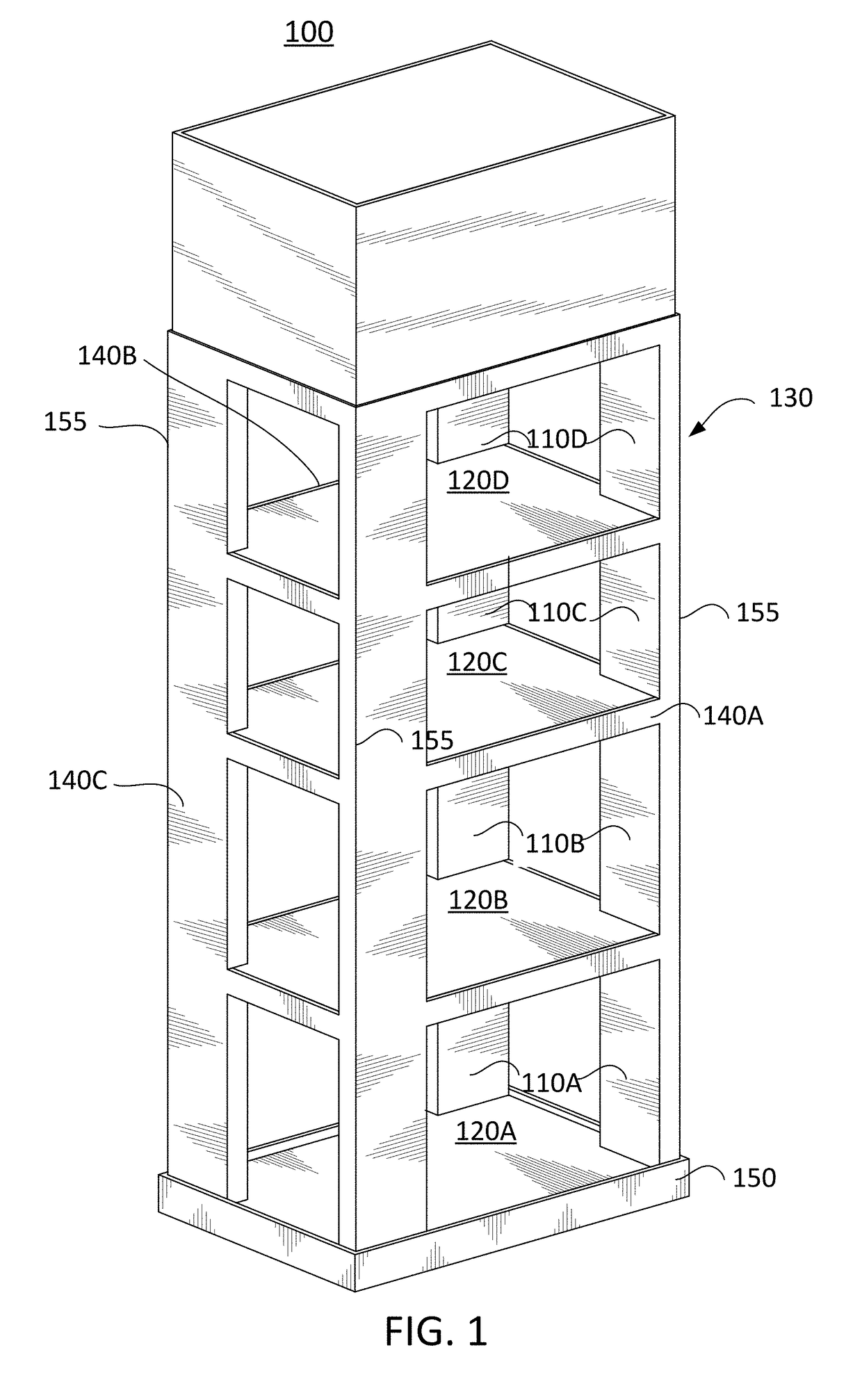
The invention is a temporary display rack with built-in support columns that provide strength and reinforcement. This rack can carry heavy products without the need for additional dividers or separates shelves, and it is easy to assemble and ship flat without tools. It also includes a mechanism to help merchants place products on the shelves and a mechanism for the manufacturer or consumer package good company to receive feedback on the marketing campaign. The rack is made from recyclable material and takes up minimal space when assembled.

Problems solved by technology

These displays are fairly costly to manufacture and ship, making them expensive to purchase and to deploy through Direct Store Delivery (DSD) systems.
Because these displays are typically shipped in an unassembled form, assembly generally requires substantial labor and use of tools to erect these displays at the point of sale.
Further, these displays are not easily recyclable and, therefore, are rarely recycled, instead ending up in landfills.
In many instances, these display stands are produced with a combination of cardboard and internal metal supports that are complicated to put together.
Furthermore, the merchants may not fill the temporary display racks with the appropriate items for the intended marketing campaign or may not place the products in the correct location on the shelves.
Shipping in this manner induces wear and tear and sometimes causes damage to the temporary display before it even reaches the merchant.
Also, the product being carried may be damaged or leak during shipment.
Furthermore, this is a costly and inefficient way of shipping the product and the temporary display rack.
Additionally, the product manufacturer or consumer package good company running the marketing campaign does not know when (or even if) the merchant places the temporary display in the retail establishment and activates the campaign.

Method used


Image

  • Display Unit with Built-in Shelving Supports
  • Display Unit with Built-in Shelving Supports
  • Display Unit with Built-in Shelving Supports

Examples


Embodiment Construction

[0068]Reference will now be made in detail to embodiments, examples of which are illustrated in the accompanying drawings. In the following detailed description, numerous specific details are set forth in order to provide a thorough understanding of the present embodiments. However, it will be apparent to one of ordinary skill in the art that the present various embodiments may be practiced without these specific details. In other instances, well-known components and methods have not been described in detail so as not to unnecessarily obscure aspects of the embodiments.

[0069]It will also be understood that, although the terms first, second, etc. may be used herein to describe various elements, these elements should not be limited by these terms. These terms are only used to distinguish one element from another (e.g., first side panel and second side panel). For example, a first element could be termed a second element, and, similarly, a second element could be termed a first element...


PUM


Abstract

Disclosed herein are various embodiments of a display unit with built-in, hollow vertical supports that are formed out of a single sheet of material. As one example, a display unit having a plurality of built-in, hollow vertical supports for supporting one or more shelves is provided. The display unit includes: a first single sheet of material folded into: (i) a plurality of vertical panels; and (ii) a first set of built-in, hollow vertical supports of the plurality of built-in, hollow vertical supports, wherein each built-in, hollow vertical support contacts one or more of the plurality of vertical panels; and a first shelf of the one or more shelves disposed within the frame and supported by each built-in, hollow vertical support of the first set of built-in, hollow vertical supports.

Description

RELATED APPLICATIONS[0001]This application claims priority to U.S. Provisional Application No. 62 / 437,025, filed on Dec. 20, 2016, which is hereby incorporated by reference in its entirety.[0002]This application is also related to the following design applications: U.S. Design Patent Application No. 29 / 588,432; U.S. Design Patent Application No. 29 / 588,433; U.S. Design Patent Application No. 29 / 588,435; U.S. Design Patent Application No. 29 / 588,436; U.S. Design Patent Application No. 29 / 588,438; U.S. Design Patent Application No. 29 / 588,440; U.S. Design Patent Application No. 29 / 588,441; U.S. Design Patent Application No. 29 / 588,442; U.S. Design Patent Application No. 29 / 588,443; and U.S. Design Patent Application No. 29 / 588,444. Each of these related design applications is hereby incorporated by reference in its entirety.TECHNICAL FIELD[0003]The disclosed embodiments relate generally to temporary display racks, display units, or stands with printed information that are used, for in...

Claims


Application Information

Patent Timeline
IPC IPC(8): A47B96/02A47B57/04A47B57/26A47B57/54
CPCA47B96/024A47B57/04A47B57/265A47B57/54A47F5/116A47B2220/0086A47B47/00
Inventor GRUPENHOF, AUSTIN G.
Owner INNERWORKINGS
Learn More