Display Panel Driving Device and Display Device

a technology of display panel and driving device, which is applied in the field of display technology, can solve the problems of poor display effect, poor display quality, and affecting the uniformity of source driver signals, so as to improve the display effect and improve the image on the small and medium-sized panels

Active Publication Date: 2018-07-12
WUHAN CHINA STAR OPTOELECTRONICS TECH CO LTD
View PDF0 Cites 3 Cited by
  • Summary
  • Abstract
  • Description
  • Claims
  • Application Information

AI Technical Summary

Benefits of technology

[0025]Compared with conventional technology, a lead at output terminal is connected to a multiplexer in the present invention. Source driver signals with different strengths through the lead are adjusted with the multiplexer to be the source driver signals with a unanimous strength. In other words, the source driver signals at different declining levels in the lead are balanced with the multiplexer and then transmitted to a plurality of data lines. Since the source driver signals with a unanimous strength enter the data line is consistent, the source driver signals in the data line is uniformed, the display of images on the small and medium-sized panel is improved, and the display effect is improved.

Problems solved by technology

However, the waveform of the source driver signal transmitted through the lead 212 at the two terminals is seriously distorted, which affects uniformity of the source driver signal, display quality of the display panel, and a poorer display effect.

Method used


Image

  • Display Panel Driving Device and Display Device
  • Display Panel Driving Device and Display Device
  • Display Panel Driving Device and Display Device

Examples


Embodiment Construction

[0032]These and other objectives of the claimed invention will no doubt become obvious to those of ordinary skill in the art after reading the following detailed description of the preferred embodiment that is illustrated in the various figures and drawings.

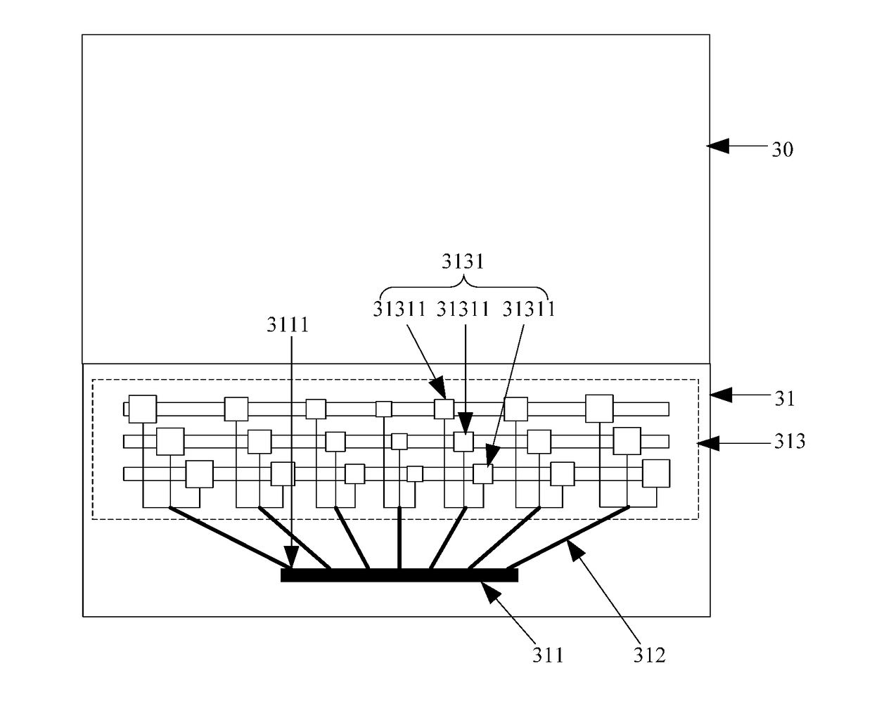
[0033]An object of the present invention is to propose a display panel driving device to fulfill the tendency of a thinned cellphone using a narrow edge bezel. A small and medium-sized panel mostly adopts the structure of a GOA and a driver chip; that is, the gate driver is integrated onto a display zone. So a source driver chip in charge of a data signal is bonded on the non-display zone. In this condition, it is necessary to adjust the source driver signal in a lead connected to a source driver signal output port of the source driver chip in charge of a data signal.

[0034]In other embodiments of the present invention, the dual-side lead routing (two or a plurality of source driver chips) is specifically for a display panel witho...


PUM


Abstract

The present disclosure proposes a display and a display panel driving device. The display panel driving device includes a source driver chip having source driver signal output ports, a leads, each lead connected to one of the source driver signal output ports, and a multiplexer connected to the leads. The multiplexer is configured to transmit the source driver signal output by each of the leads to data lines on the display panel, and configured to adjust the strength of the source driver signal output by each of leads if the strength is not unanimous so that the source driver signals with a single strength enters the data lines. The display includes a display panel and the display panel driving device. Display uniformity of images shown on the panel is improved.

Description

BACKGROUND OF THE INVENTION1. Field of the Invention[0001]The present invention relates to the field of display technology, and more particularly, to a display panel driving device and a display device.2. Description of the Prior Art[0002]To fulfill the tendency of a thinned cellphone using a narrow bezel, a small and medium-sized panel comprises a gate driver on array (GOA) plus a driver chip; that is, the gate driver is integrated onto a display zone. So a source driver chip in charge of a data signal is bonded on the non-display zone.[0003]FIG. 1 is a schematic diagram of the structure of a conventional display device. The conventional display device comprises a display panel 20 and a display panel driving device 21. The display panel driving device 21 comprises a source driver chip 211, a lead 212, and a multiplexer 213. The source driver chip 211 is connected to a data line through a set of sectoral conductors. The set of sectoral conductors comprise a plurality of leads 212. E...

Claims


Application Information

Patent Timeline
Patent Type & Authority Applications(United States)
IPC IPC(8): G09G3/20H01L27/12H01L29/786
CPCG09G3/2092H01L27/124H01L29/78696G09G2310/0297G09G2300/0426G09G2320/0233G09G3/2077H01L27/1214
Inventor XING, ZHENZHOU
Owner WUHAN CHINA STAR OPTOELECTRONICS TECH CO LTD
Why Eureka
Try Eureka