
Electrodeposition System and Electrodeposition Method

a technology of electrodeposition system and electrodeposition method, which is applied in the direction of electrolysis components, electrolysis coatings, coatings, etc., can solve the problems of significant deformation of the final quality of the coating of the coated object, limited communication with the outside, and degradation of the final quality, so as to prevent the final quality of the coating, increase the initial cost and running cost, and the effect of increasing the system siz

Active Publication Date: 2018-07-19
MAZDA MOTOR CORP +1
View PDF2 Cites 0 Cited by
  • Summary
  • Abstract
  • Description
  • Claims
  • Application Information

AI Technical Summary

Benefits of technology

The patent proposes a method for coating steel plates with a coating material-containing aqueous solution during a drying process. The method prevents degradation of the coating quality and avoids problems such as increased system size, costs, and reduced reliability. The technical effect of this method is a reduction in energy loss and lower running costs.

Problems solved by technology

The steel plate mating portions are gaps between steel plates, the entrances of which are narrowed due to steel plates being brought into contact with each other when the object to be coated is processed, so that communication with the outside is limited.
Conventionally, there is a problem in which the final quality of the coating of a coated object is significantly degraded due to the above-described phenomenon (degradation in the final quality of a coating due to so-called “secondary sagging”).

Method used


Image

  • Electrodeposition System and Electrodeposition Method
  • Electrodeposition System and Electrodeposition Method
  • Electrodeposition System and Electrodeposition Method

Examples


first embodiment

[0079]The following describes a first embodiment of an electrodeposition system and an electrodeposition method according to the present invention with reference to the drawings.

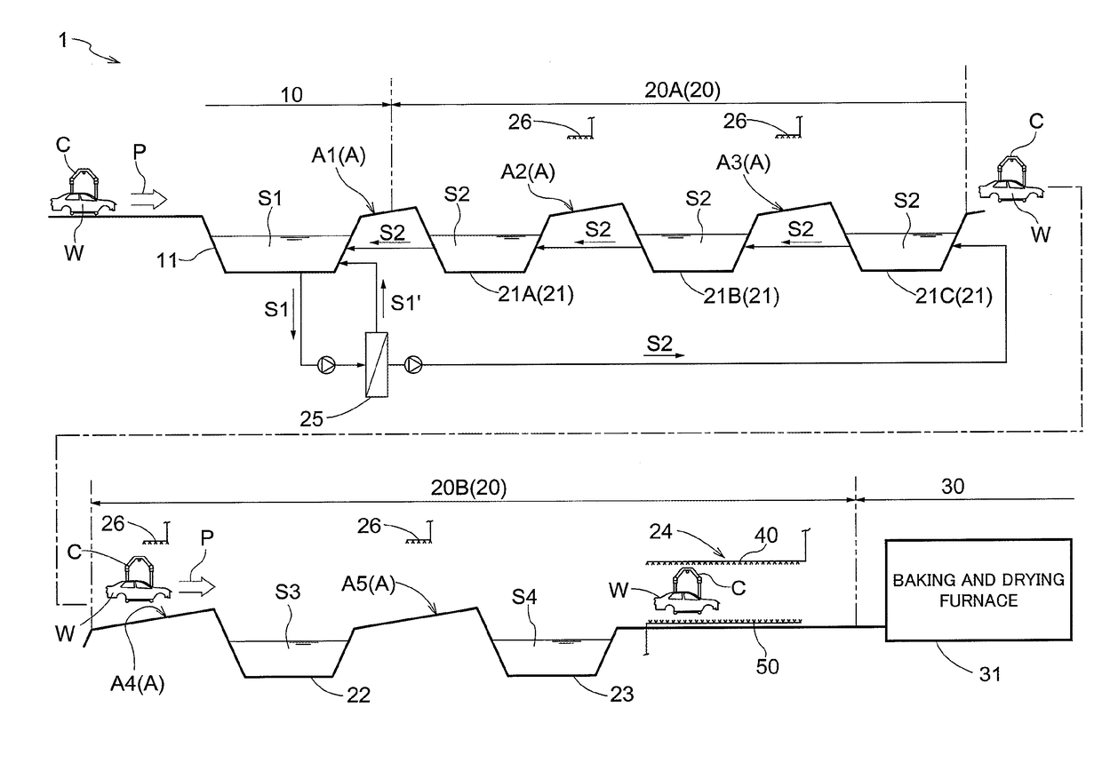
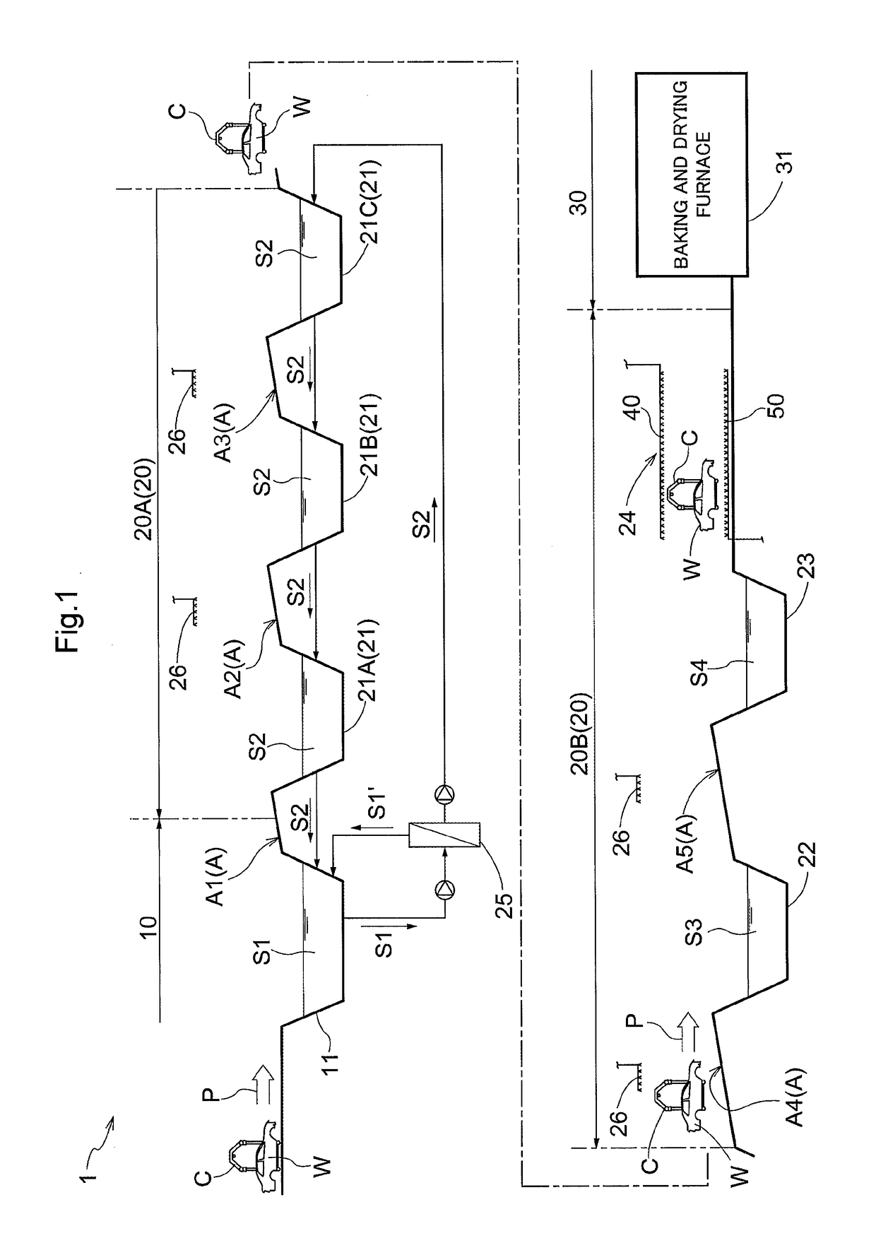
[0080]FIG. 1 shows an overall configuration of an electrodeposition system 1. The electrodeposition system 1 is provided with an electrodeposition zone 10, a washing zone 20, and a drying zone 30, which are zones in which coating-target objects W (the bodies of automobiles in the present embodiment) are processed.

[0081]The electrodeposition system 1 is also provided with a conveyance means C such as a conveyor, which sequentially conveys the coating-target objects W at predetermined conveyance intervals. The conveyance means C holds each of the coating-target objects W to be conveyed, using an appropriate jig such as a hanger receiving tool.

[0082]That is, in the electrodeposition system 1, the conveyance means C conveys the coating-target objects W to the electrodeposition zone 10, the washing zone 20, and t...

second embodiment

[0169]Next, the following describes a second embodiment of an electrodeposition system and an electrodeposition method according to the present invention with reference to the drawings.

[0170]Note that differences from the electrodeposition system in the first embodiment will be mainly described below. Therefore, features that are not specifically described are the same as those of the first embodiment.

[0171]Also, the same components as those in the electrodeposition system in the first embodiment are assigned the same reference numerals as in the first embodiment.

[0172]FIG. 5 shows an electrodeposition system 1 according to the second embodiment. From this electrodeposition system 1, the water washing tank 22 (i.e. the water washing tank used to wash a coating-target object W by immersing the coating-target object W in the room-temperature pure water S3 stored in the tank) of the electrodeposition system in the first embodiment is omitted.

[0173]That is, the downstream washing zone 2...


PUM

PropertyMeasurementUnit
Temperatureaaaaaaaaaa

Abstract

In an electrodeposition system, the final quality of a coating is prevented from being degraded due to a coating material-containing aqueous solution flowing out of a steel plate mating portion during a drying process, while derivative problems such as an increase in the size of the system, an increase in the initial costs and the running costs, and a decrease in reliability are avoided. A washing zone that is subsequent to an electrodeposition zone in which an object to be coated is immersed in a coating material solution for electrodeposition so that a coating is formed on a surface of the object to be coated is provided with: a hot water washing tank in which the coated object is washed by being immersed in high-temperature washing water in the tank; and a spray washer that sprays a steel plate mating portion of the coated-object with high-temperature washing water, subsequent to washing in the hot water washing tank.

Description

TECHNICAL FIELD[0001]The present invention relates to an electrodeposition system and an electrodeposition method.[0002]More specifically, the present invention relates to an electrodeposition system that includes: an electrodeposition zone in which an object to be coated is immersed in a coating material solution for electrodeposition so that a coating is formed on the surface of the object to be coated; a washing zone in which the coated object having the coating formed on the surface thereof in the electrodeposition zone is washed using washing water; and a drying zone in which the coated object washed in the washing zone is heated so that the coating of the coated object is hardened and dried, and the present invention also relates to an electrodeposition method using the electrodeposition system.BACKGROUND ART[0003]An object to be coated using electrodeposition, such as the body of an automobile, often includes steel plate mating portions, such as a bag-shaped portion in a door...

Claims


Application Information

Patent Timeline
IPC IPC(8): C25D21/08C25D13/22C25D21/02
CPCC25D21/08C25D13/22C25D21/02C25D13/24C25D13/12
Inventor KATAYAMA, KATSUONAKAGAWA, HIROYUKITSUJI, HIROAKIKAWANAMI, AKIRAKOUNO, SHINTAROUTOOKA, SHIGETAKAKUROKAWA, SHIZUKO
Owner MAZDA MOTOR CORP
Learn More