
X-ray diffraction measurement method and apparatus

a technology of x-ray diffraction and measurement method, applied in the direction of measurement devices, instruments, scientific instruments, etc., can solve the problems of large apparatus size and increase in manufacturing costs, and achieve the effect of effective measuremen

Active Publication Date: 2018-07-19
HONDA MOTOR CO LTD
View PDF0 Cites 6 Cited by
  • Summary
  • Abstract
  • Description
  • Claims
  • Application Information

AI Technical Summary

Benefits of technology

The present invention provides an X-ray diffraction measurement method and apparatus that can effectively measure an object by a one-time X-ray detection operation. By inclining the slit in a unique way and detecting the X-rays, the diffraction position and angle can be determined, and a diffraction profile can be calculated based on the detected X-ray image. This allows for accurate and efficient measurement of the object. Additionally, the shielding plate can be rotated to change the direction of slit inclination for different object types. Overall, the invention enables fast and accurate X-ray diffraction measurements.

Problems solved by technology

However, with the apparatus proposed in Japanese Laid-Open Patent Publication No. 2015-132527, since a rotation mechanism for rotating the slit plate is required, the size of the apparatus is large in scale, which results in an increase in manufacturing costs.

Method used


Image

  • X-ray diffraction measurement method and apparatus
  • X-ray diffraction measurement method and apparatus
  • X-ray diffraction measurement method and apparatus

Examples


Embodiment Construction

[0030]A preferred embodiment of an X-ray diffraction measurement method according to the present invention in relation to an X-ray diffraction measurement apparatus will be presented and described below with reference to the accompanying drawings.

[Configuration of X-Ray Diffraction Measurement Apparatus 10]

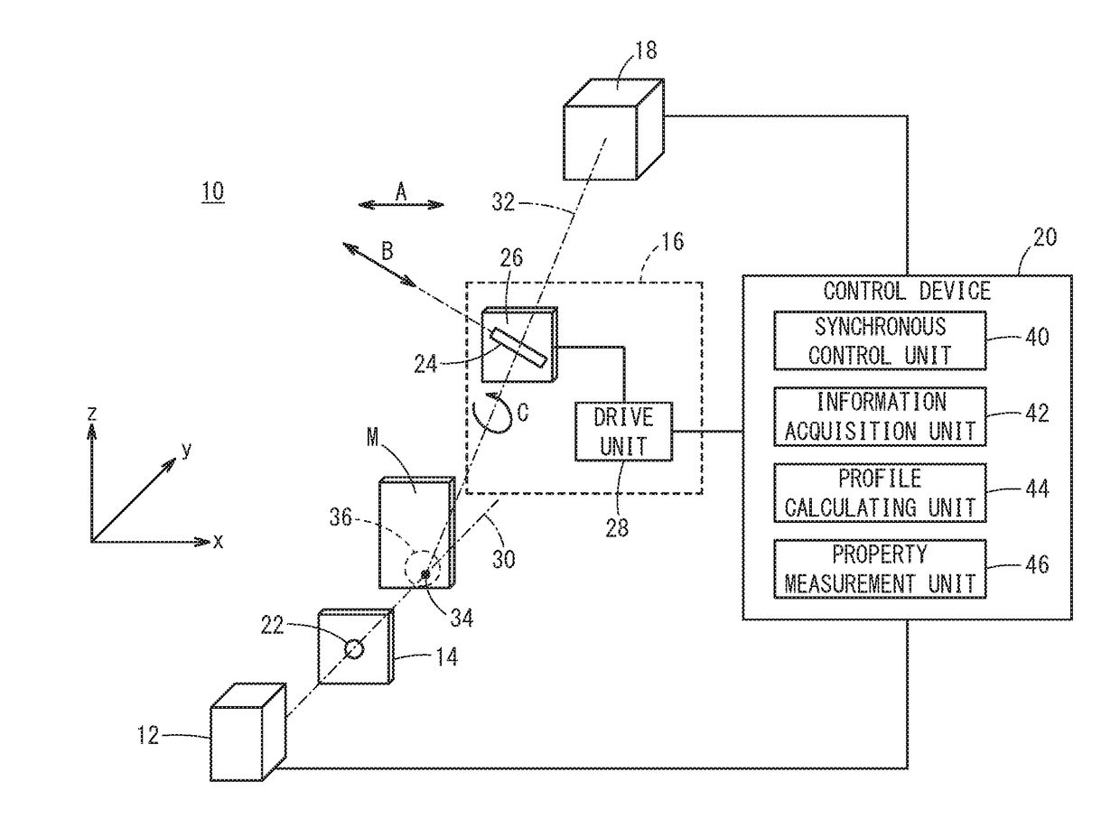
[0031]FIG. 1 is a configuration diagram of an X-ray diffraction measurement apparatus 10 according to an embodiment of the present invention. The X-ray diffraction measurement apparatus 10 is an apparatus adapted to measure properties of an object to be measured M, by detecting an X-ray diffraction pattern of X-rays produced by the object to be measured M. According to the present embodiment, an apparatus configuration is shown in which a transmission type of X-ray diffraction method is performed. However, an apparatus configuration may also be adopted which is applicable to a reflection type of X-ray diffraction method.

[0032]The X-ray diffraction measurement apparatus 10 is const...


PUM

PropertyMeasurementUnit
thicknessaaaaaaaaaa
aaaaaaaaaa
diffraction angleaaaaaaaaaa

Abstract

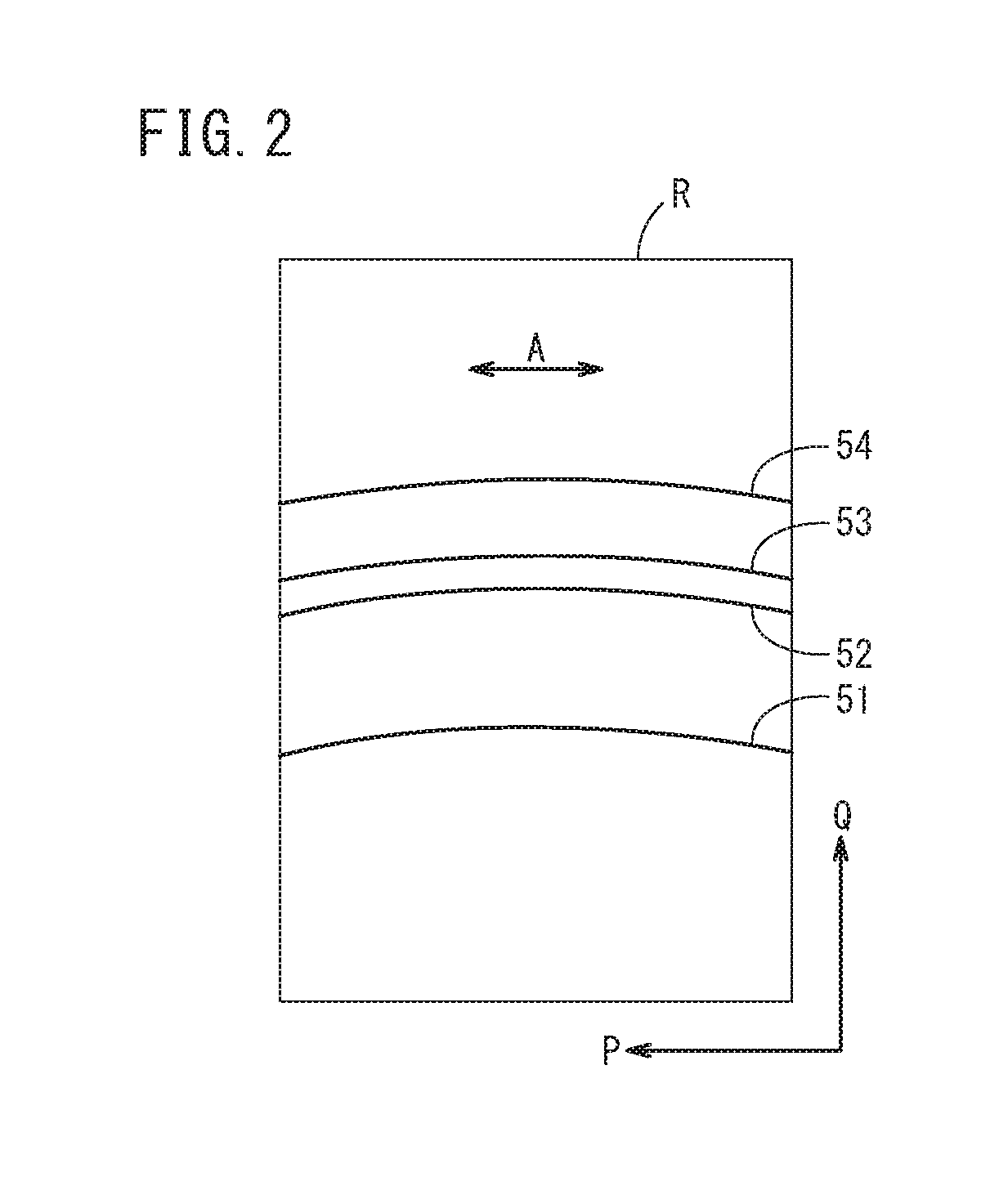
An X-ray diffraction measurement method includes an arranging step of arranging a shielding plate and a two-dimensional detector on an outgoing optical axis, and a calculating step of calculating a diffraction profile indicating an X-ray intensity with respect to a diffraction angle of the object to be measured, on the basis of a two-dimensional X-ray image detected by the two-dimensional detector. In the arranging step, the shielding plate is arranged in a manner so that the slit is inclined at least in a direction about the outgoing optical axis with respect to an orthogonal direction which is orthogonal to both the incident optical axis and the outgoing optical axis.

Description

CROSS-REFERENCE TO RELATED APPLICATION[0001]This application is based upon and claims the benefit of priority from Japanese Patent Application No. 2017-007155 filed on Jan. 19, 2017, the contents of which are incorporated herein by reference.BACKGROUND OF THE INVENTIONField of the Invention[0002]The present invention relates to an X-ray diffraction measurement method and apparatus for measuring properties of an object to be measured by detecting an X-ray diffraction pattern of X-rays produced by the object to be measured.Description of the Related Art[0003]Conventionally, an X-ray diffraction measurement method has been known for measuring properties of an object to be measured by detecting a diffraction pattern (hereinafter also simply referred to as a “pattern”) by irradiating X-rays toward the object to be measured. For example, in order to improve measurement efficiency, various methods have been proposed in which a combination of a two-dimensional slit and a two-dimensional det...

Claims


Application Information

Patent Timeline
Patent Type & Authority Applications(United States)
IPC IPC(8): G01N23/207
CPCG01N23/207G01N2223/0566G01N23/2055G01N2223/316G01N2223/32G01N2223/323
Inventor SATO, KENJINAKAO, KAZUHITO
Owner HONDA MOTOR CO LTD
Learn More