
Tread wear indicator

Inactive Publication Date: 2018-07-26
THE GOODYEAR TIRE & RUBBER CO
View PDF4 Cites 13 Cited by
  • Summary
  • Abstract
  • Description
  • Claims
  • Application Information

AI Technical Summary

Benefits of technology

The patent is describing a design feature for a tire tread that is called a "sipe." This sipe is a small, narrow opening that helps improve the tire's traction on the road. The technical effect of this design is better control and performance of the tire on various road surfaces.

Problems solved by technology

In the pneumatic tire art, it is known that, as the tread of the tire wears away, the ability to maintain traction may diminish on wet or snow-covered roads.
However, such tread wear indicators may undesirably interfere with the flow of water and materials through the groove.
In addition, due to their placement in a groove, they may be difficult for a user to see.
However, many such prior art indicators have undesirably interfered with tread performance and / or were difficult for a user to see.
An additional disadvantage of prior art indicators that were disposed in the tread is that the indicators were of a simple configuration which wore away before the user saw or understood the wear indication.
While such sensors are suitable for their intended purpose, they add to the cost of the tire.

Method used


Image

  • Tread wear indicator
  • Tread wear indicator
  • Tread wear indicator

Examples


first embodiment

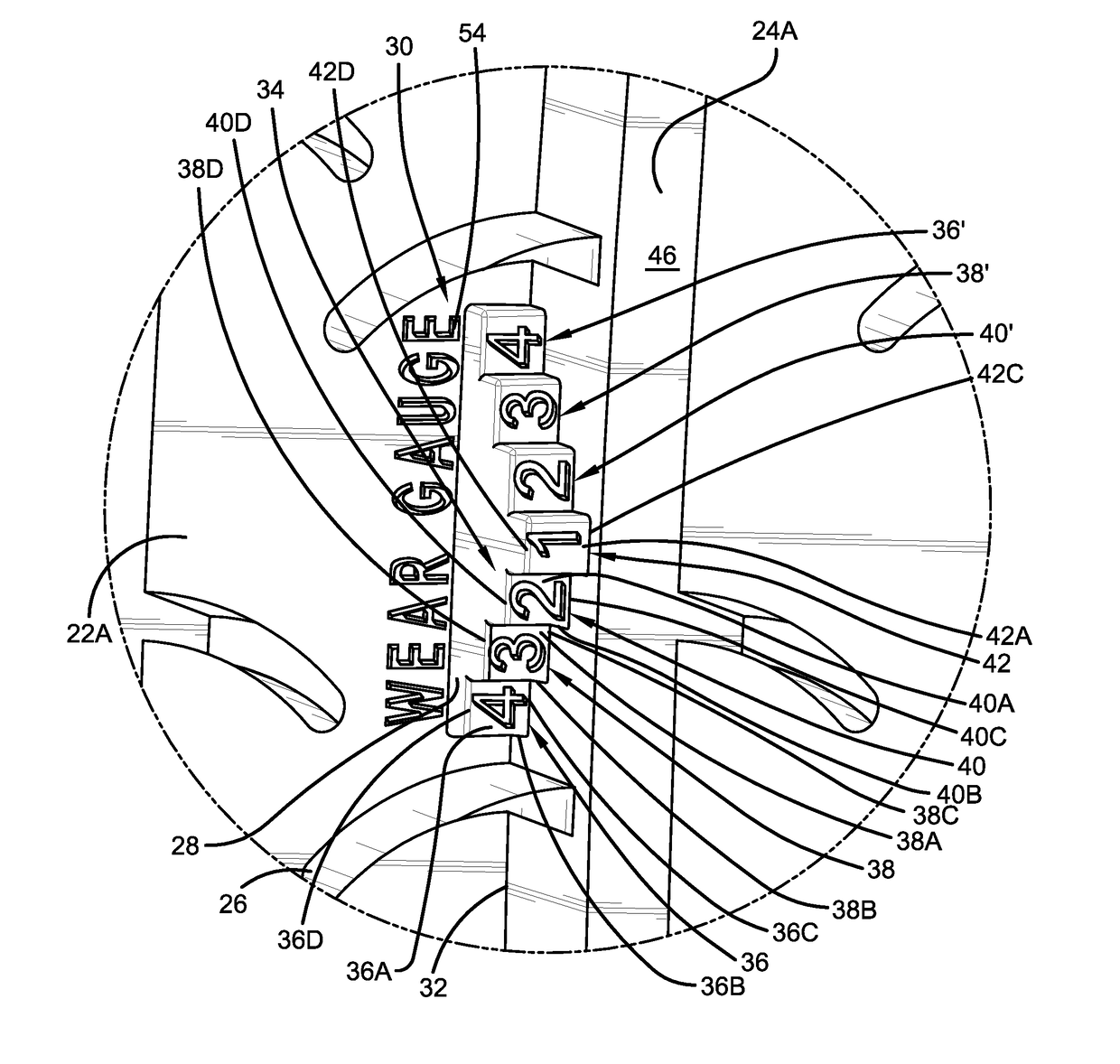
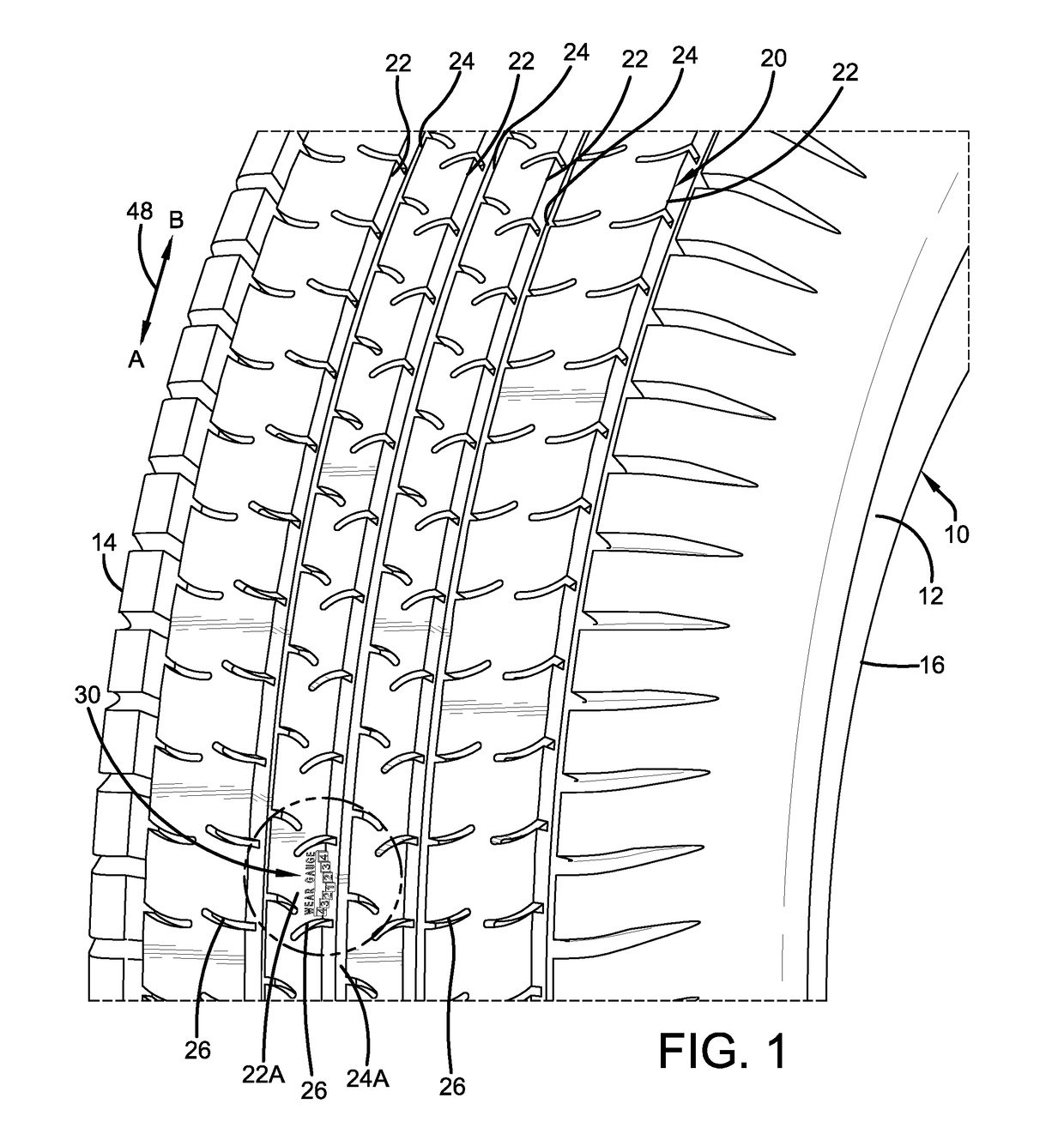
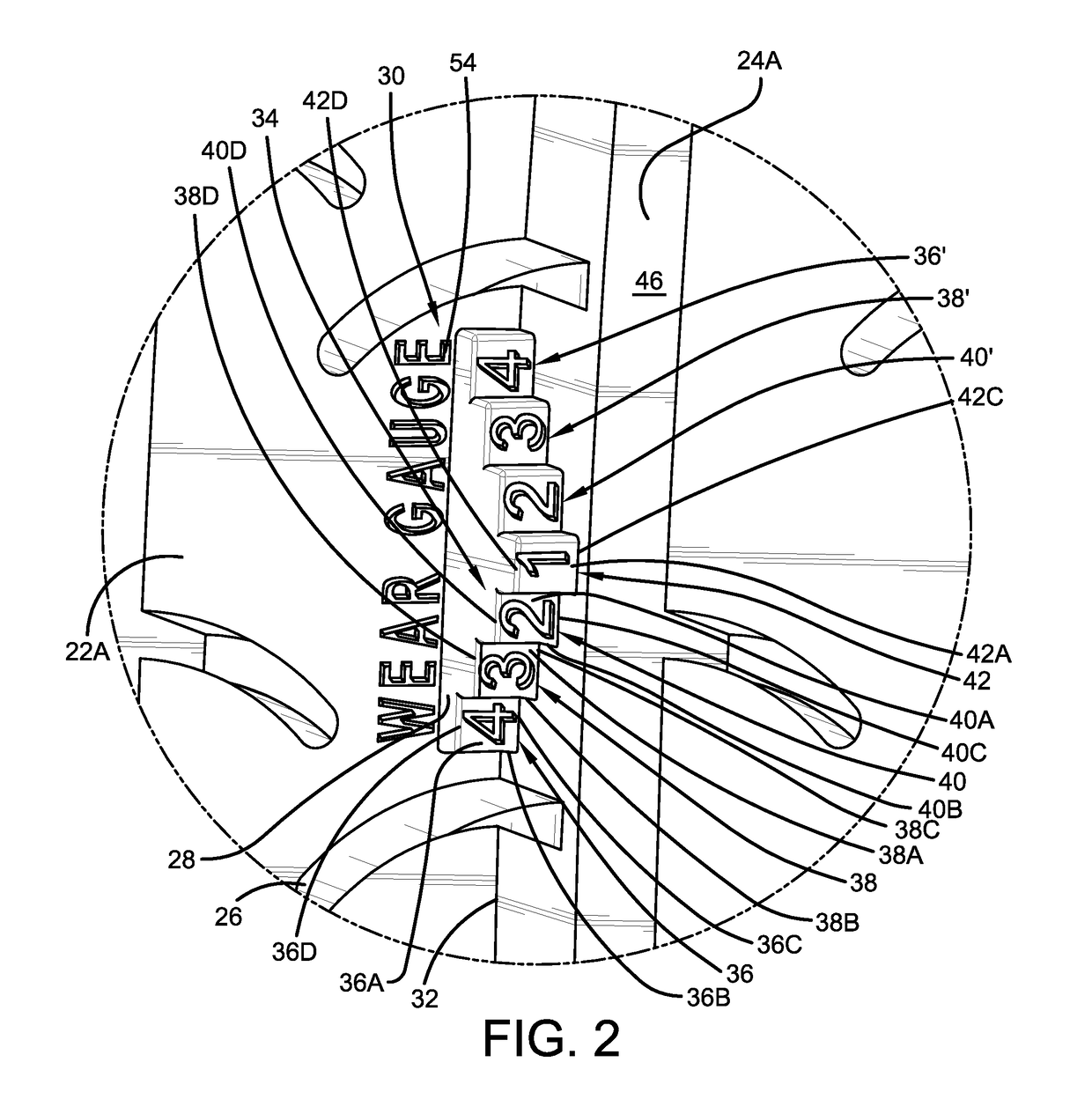
[0031]Referring now to FIGS. 2 through 4, the tread wear indicator 30 is formed at the edge of the selected tread element 22A adjacent a selected one of the circumferential grooves 24A. The first embodiment tread wear indicator 30 is formed with a double staircase configuration. More particularly, a plurality of step elements 34 descends from the radially outward tread surface 32 toward the bottom or base surface 46 of the selected circumferential groove 24A. The tread wear indicator includes at least two elements 34, and preferably four or more elements. As will be described below, each element 34 is similar to the other elements in shape and configuration.

[0032]For example, a first step 36 includes an axially-extending surface 36A that is approximately parallel to and radially inward of the outward tread surface 32. Preferably, the axially-extending surface 36A is formed with a square or rectangular shape. A radially-extending surface 36B extends from the radially outward tread su...

second embodiment

[0049]By being located in the selected tread element 22A adjacent the selected groove 24A, the tread wear indicator 52 is easy for a user to see, does not interfere with the performance of the grooves 24 and 26 or the tread 20, and is economical to form.

[0050]Turning to FIG. 10, the tread wear indicator 52 preferably is formed in the tire 10 when the tire is cured. To form the tread wear indicator 52, a die insert 56 is formed with the above-described features of the tread wear indicator. The die insert 56 is disposed in a corresponding opening formed in the tire curing mold, and when the tread 20 is formed on the tire 10 during curing, the tread wear indicator 30 is also formed. The die insert 56 may be 3D printed, cast or fabricated, and may be formed of any suitable mold material, including steel, aluminum and alloys thereof.

[0051]The present invention also includes a method of forming a tread wear indicator 30, 52 in a tire 10 and a method of using a tread wear indicator 30, 52 ...


PUM

PropertyMeasurementUnit
Fractionaaaaaaaaaa
Fractionaaaaaaaaaa
Fractionaaaaaaaaaa

Abstract

A tread wear indicator for a tire is provided. The tire includes a pair of sidewalls and a tread and the tread includes a plurality of tread elements defined by circumferential grooves and lateral grooves. The tread wear indicator is formed in a selected one of the tread elements adjacent a selected one of the circumferential grooves. The indicator includes a plurality of step elements descending from a radially outward surface of the selected one of the tread elements toward the base of the selected one of the circumferential grooves. Each step element includes an axially-extending surface that is approximately parallel to and is radially inward of the radially outward surface of the selected one of the tread elements, and a radially-extending surface that extends approximately perpendicular to the axially-extending surface. The axially-extending surface of each step element is formed with indicia visible to a user of the tire.

Description

FIELD OF THE INVENTION[0001]The invention relates to pneumatic tires and to tread wear indicators for such tires. More particularly, the invention is directed to a visual tread wear indicator that is economical to form and is easy for a user to read.BACKGROUND OF THE INVENTION[0002]In the pneumatic tire art, it is known that, as the tread of the tire wears away, the ability to maintain traction may diminish on wet or snow-covered roads. Accordingly, once the tread is worn beyond a certain tread depth, the tire should be replaced to maintain adequate traction.[0003]In order to inform a vehicle user when a tire may need to be replaced due to tread wear, prior art tread wear indicators were developed. For example, some tread wear indicators involved providing features molded in the base of the circumferential grooves of the tire tread. However, such tread wear indicators may undesirably interfere with the flow of water and materials through the groove. In addition, due to their placeme...

Claims


Application Information

Patent Timeline
IPC IPC(8): B60C11/24
CPCB60C11/24B60C11/04B60C2011/0381B29D2030/0612B29D30/0606
Inventor SERVA, JESSE BRIANLAURICH, THOMAS ANDREWMUNDAY, DENISE MONKNOWACKI, MARC CHRISTOPHERRISMILLER, JASON DAVIDCROYLE, WARREN LEE
Owner THE GOODYEAR TIRE & RUBBER CO
Learn More