This helps you quickly interpret patents by identifying the three key elements:
Problems solved by technology
Method used
Benefits of technology
Benefits of technology
The present invention relates to a vehicle display device that can adjust the position and size of virtual images based on the user's viewpoint position. This helps to provide appropriate information to the user without discomfort caused by changes in viewpoint position. Additionally, the device ensures that a range of distance on a road surface of a scene, on which a virtual image related to an image element is superimposed, remains constant regardless of changes in the user's viewpoint position. This reduces the processing load on the image generation unit and enables the device to collectively determine the display positions and sizes of all the image elements based on changes in the user's viewpoint position. Overall, the invention improves the user's experience and provides more relevant information while driving.
Problems solved by technology
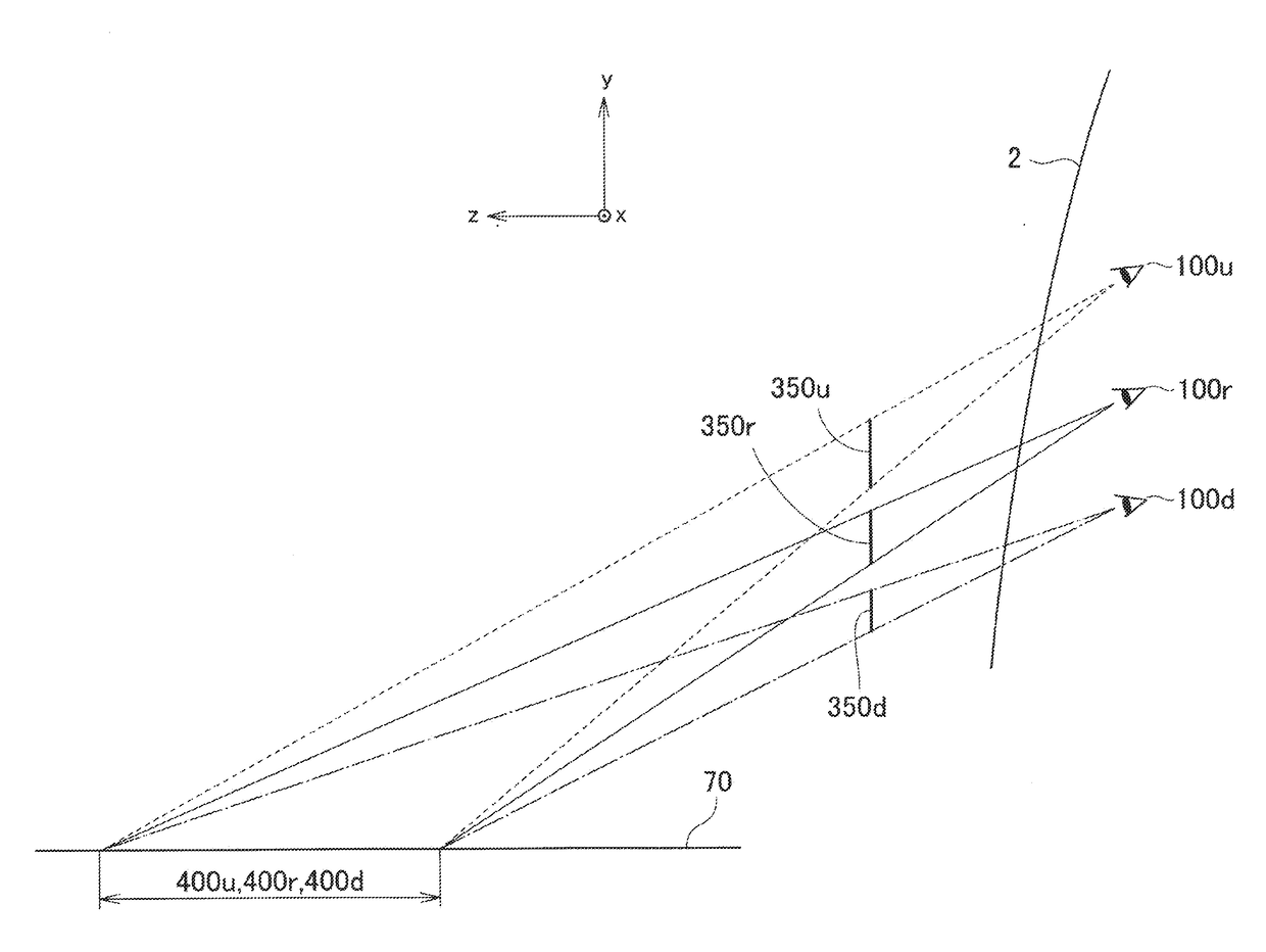
Thus, as the viewpoint position of the user sitting in the driver seat changes, an object in the scenery where the virtual image is superimposed deviates, causing a possibility of giving an uncomfortable feeling to the user.
Method used
Image
Click on the blue label to locate the original text in one second.
Reading with bidirectional positioning of images and text.
Examples
first embodiment
1. First Embodiment
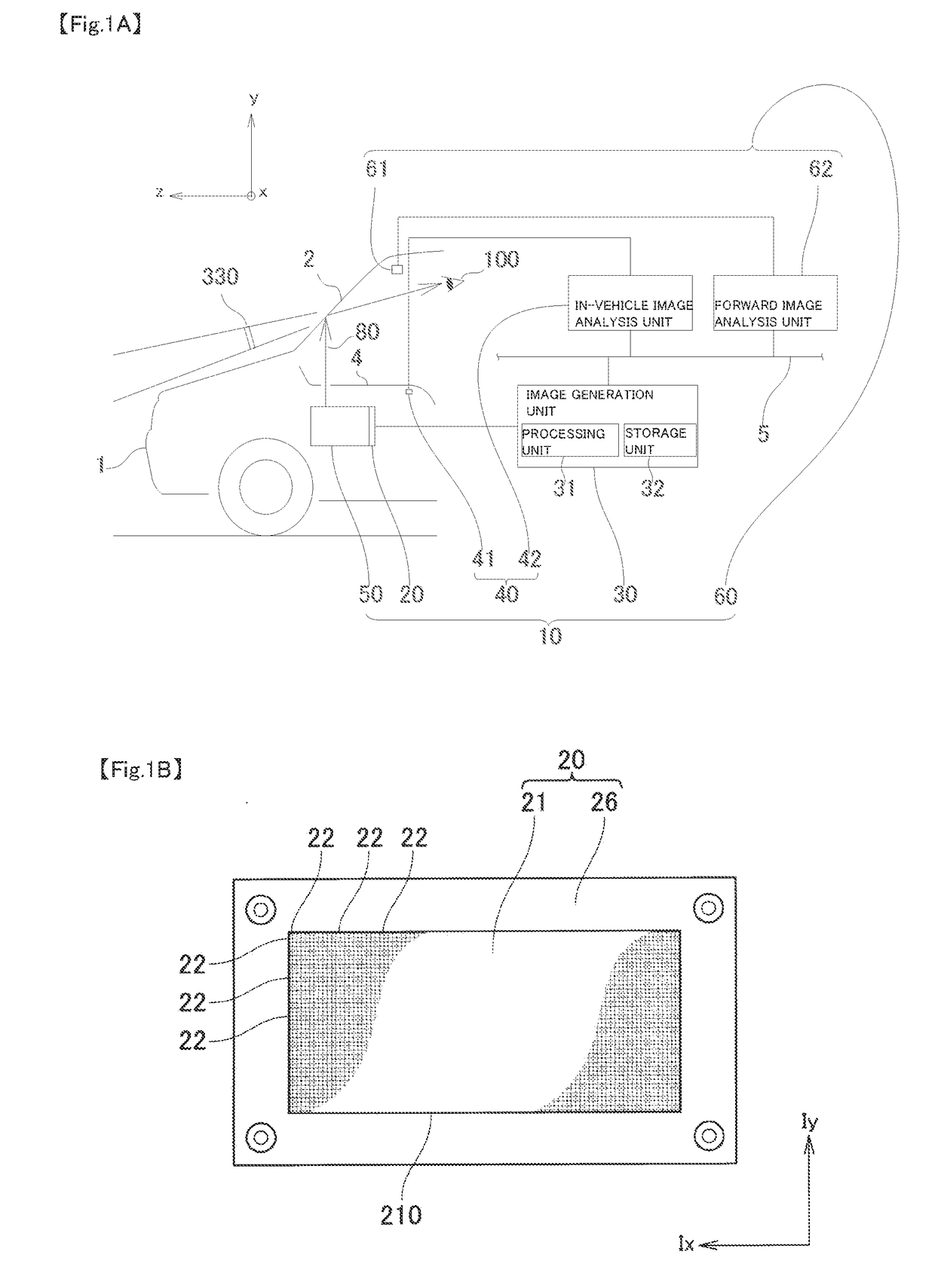
[0056]An example of the entire configuration of a vehicle display device 10 of the present invention will be described with reference to FIGS. 1 A, 1 B, and 1 C. In order to facilitate the following explanation, as shown in FIG. 1 A, in a real space, for example, a z-axis is defined in a front-rear direction of a vehicle with a traveling direction of a vehicle 1 as a front direction of the vehicle, a y-axis is defined in a vertical direction, and an x-axis is defined in a left-right direction (the left-right direction of the vehicle) facing the front direction of the vehicle.
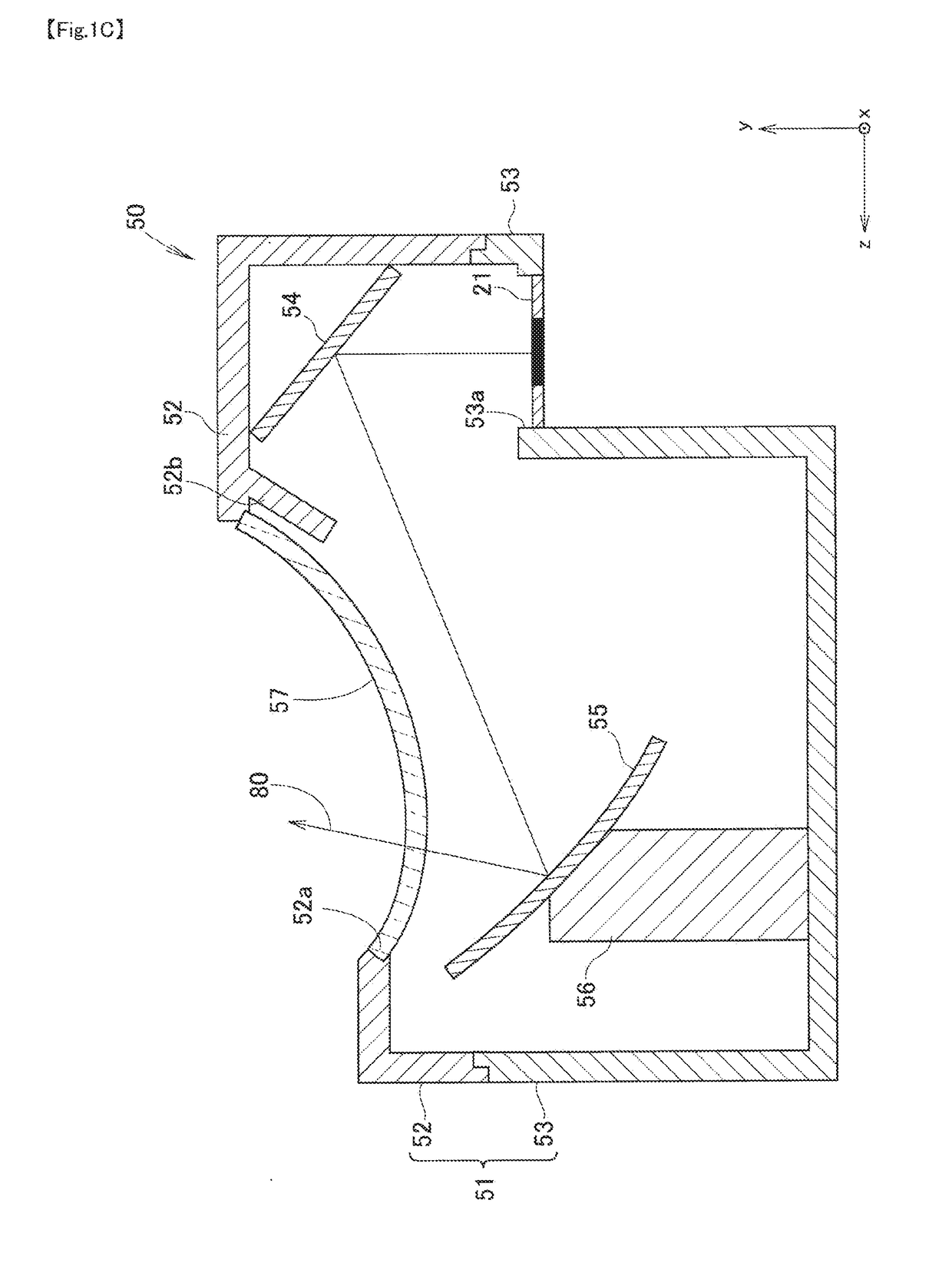
[0057]As shown in FIG. 1 A, the vehicle display device 10 includes an image display unit 20, an image generation unit 30, a viewpoint position acquisition unit 40, a projection unit 50, and a forward information acquisition unit 60.
[0058]As shown in FIG. 1 B, the image display unit 20 has a display surface 21 capable of displaying an image. An image displayable area 210 of the display surface ...
second embodiment
2. Second Embodiment
[0106]A second embodiment of the vehicle display device 10 of the present invention will be described with reference to FIGS. 6 and 7. Since the second embodiment is a modification of the above-described first embodiment, only portions different from the first embodiment will be described, and descriptions of similar portions will be omitted. In addition, the same reference numerals as those used in the description of the first embodiment are used for constituent elements common to the first embodiment.
[0107]In the first embodiment of the above-described vehicle display device 10, a user sitting in a driver seat of the vehicle 1 is allowed to properly view the virtual image superimposed mark 350 informing the presence of a notifying object in front of the vehicle 1. In the second embodiment of the vehicle display device 10 described below, a user sitting in a driver seat of the vehicle 1 is allowed to properly view not only the virtual image superimposed mark 350...
third embodiment
3. Third Embodiment
[0123]A third embodiment of the vehicle display device 10 of the present invention will be described with reference to FIGS. 8, 9, 10, 11, and 12. Since the third embodiment is a modification of the first embodiment and the second embodiment described above, only portions different from the first embodiment and the second embodiment will be described, and descriptions of similar portions will be omitted. In addition, the same reference numerals as those used in the description of the first embodiment or the second embodiment are used for constituent elements common to the first embodiment or the second embodiment.
[0124]In the second embodiment of the vehicle display device 10 described above, the image generation unit 30 directly determines the display position and the display size of the superimposed mark 250 on the display surface 21 and the display position of the superimposed mark 270 on the display surface 21, in accordance with the change in the user viewpoi...
PUM
Abstract
A vehicle display device includes: a viewpoint position acquisition unit acquiring a user viewpoint position of a user seated in a driver seat of a vehicle; a forward information acquisition unit acquiring forward information of the vehicle; an image generation unit generating an image obtained by reflecting the forward information included within a prescribed area among the forward information acquired by the forward information acquisition unit; an image display unit having a display surface capable of displaying the image generated; and a projection unit projecting the image toward a vehicle's translucent member such that a virtual image is visible to the user. The image generation unit determines the position and the size of a first image element to be displayed, among image elements included in the generated image, on the display surface, according to the user viewpoint position in the vertical direction acquired by the viewpoint position acquisition unit.
Description
TECHNICAL FIELD[0001]The present invention relates to a vehicle display device. More particularly, the present invention relates to a vehicle display device capable of providing appropriate information to a user without being affected by a change in a viewpoint position of a user.BACKGROUND ART[0002]As a vehicle display device, there is a so-called head-up display, which allows a user sitting in a driver seat to visually recognize a virtual image by projecting a display image on a translucent member such as a front windshield of a vehicle and using the light of a display image reflected by the front windshield. In such a vehicle display device, a virtual image is visually recognized by a user sitting in a driver seat so that a virtual image is formed on a vehicle traveling direction side (vehicle front side) with respect to a front windshield of a vehicle. A general configuration of such a vehicle display device includes, for example, an image display unit for displaying a display i...
Claims
Application Information
Patent Timeline
Application Date:The date an application was filed.
Publication Date:The date a patent or application was officially published.
First Publication Date:The earliest publication date of a patent with the same application number.
Issue Date:Publication date of the patent grant document.
PCT Entry Date:The Entry date of PCT National Phase.
Estimated Expiry Date:The statutory expiry date of a patent right according to the Patent Law, and it is the longest term of protection that the patent right can achieve without the termination of the patent right due to other reasons(Term extension factor has been taken into account ).
Invalid Date:Actual expiry date is based on effective date or publication date of legal transaction data of invalid patent.

