Light emitting display device

a technology of light-emitting display and display device, which is applied in the direction of solid-state devices, electric lighting sources, electric light sources, etc., can solve the problems of reducing the efficiency of light transmission to the outside, and achieve the effect of improving color reproducibility and reducing color shi

Active Publication Date: 2018-07-26
SAMSUNG DISPLAY CO LTD
View PDF14 Cites 33 Cited by
  • Summary
  • Abstract
  • Description
  • Claims
  • Application Information

AI Technical Summary

Benefits of technology

[0028]According to the exemplary embodiment of the present disclosure, the light-emitting display device with improved color reproducibility and reduced color shift can be implemented.

Problems solved by technology

However, since light generated from the emission layer is partially or totally reflected between the emission layer and the electrodes, efficiency of light transmitted to the outside decreases.

Method used


Image

  • Light emitting display device
  • Light emitting display device
  • Light emitting display device

Examples


Embodiment Construction

[0044]The present disclosure will be described more fully hereinafter with reference to the accompanying drawings, in which exemplary embodiments of the disclosure are shown. As those skilled in the art would realize, the described embodiments may be modified in various different ways, all without departing from the spirit or scope of the present disclosure.

[0045]Parts that are irrelevant to the description will be omitted to clearly describe the present disclosure, and like reference numerals designate like elements throughout the specification.

[0046]Further, in the drawings, the size and thickness of each element are arbitrarily illustrated for ease of description, and the present disclosure is not necessarily limited to those illustrated in the drawings. In the drawings, the thickness of layers, films, panels, regions, etc. are exaggerated for clarity. In the drawings, for ease of description, the thicknesses of some layers and regions are exaggerated.

[0047]In addition, It will b...


PUM


Abstract

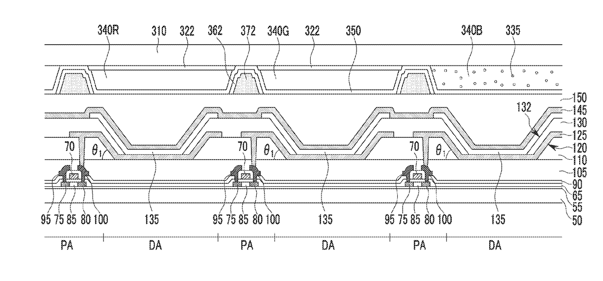
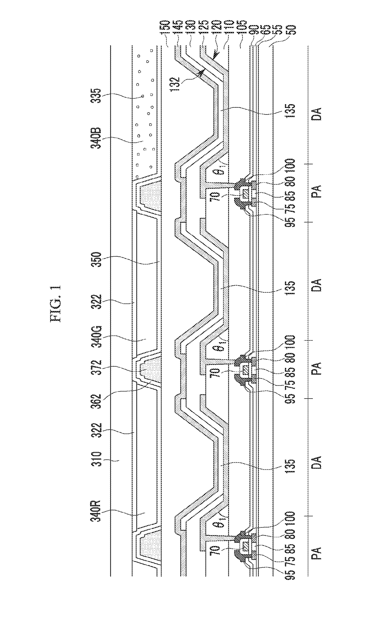
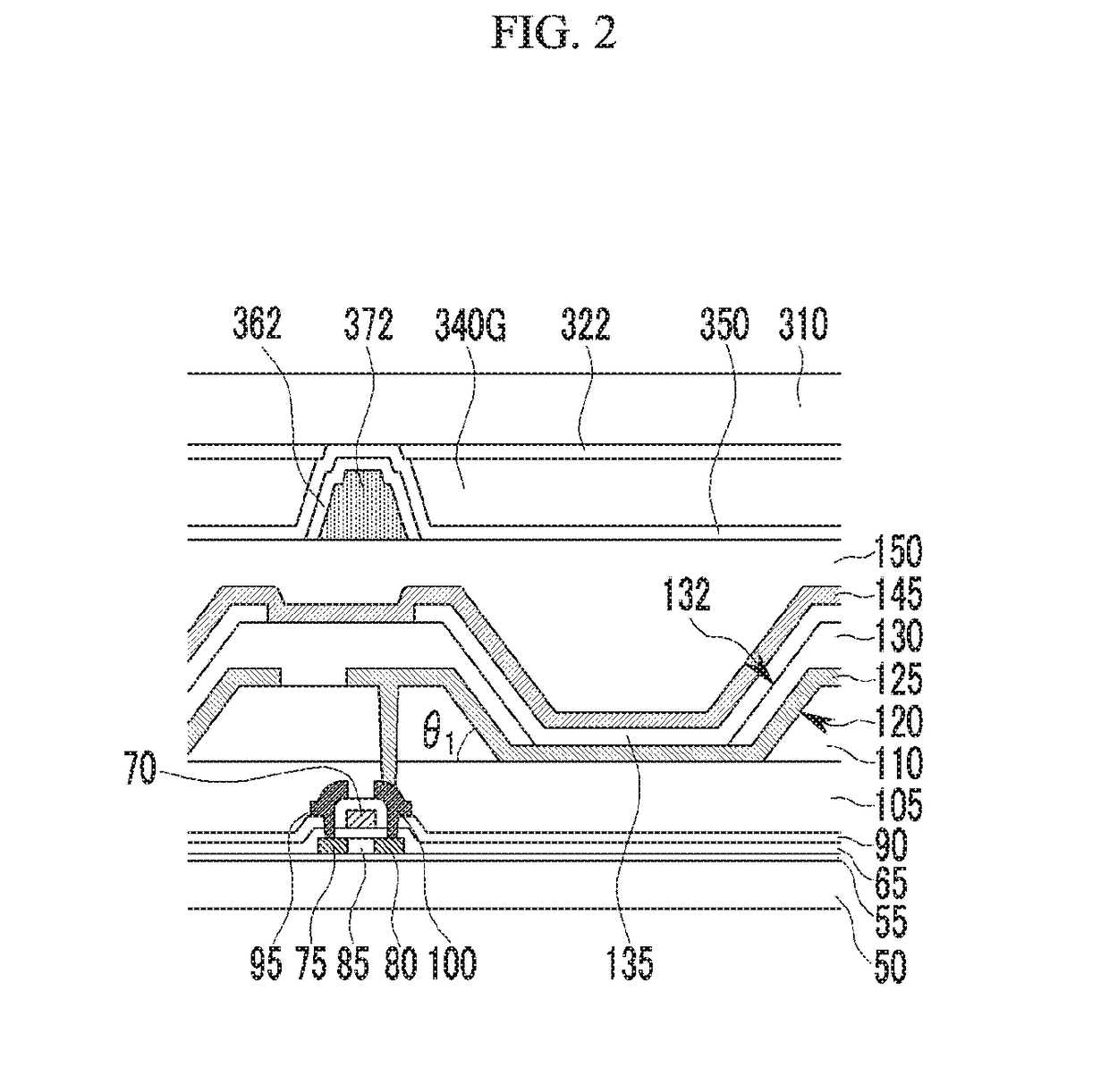
A light emitting display device according to an exemplary embodiment of the present disclosure includes: a first substrate; an insulating layer disposed on the first substrate and having an inclined portion; a first electrode disposed on the insulating layer; a light-emitting layer disposed on the first electrode; a second electrode disposed on the light-emitting layer; and a plurality of color conversion layers disposed on the second electrode. The first electrode includes an inclined portion that is inclined along the inclined portion of the insulating layer based on a surface parallel to the first substrate, and the light-emitting layer includes semiconductor nano-particles.

Description

CROSS-REFERENCE TO DELATED APPLICATION[0001]This application claims priority to and the benefit of Korean Patent Application No. 10-2017-0011931 filed in the Korean Intellectual Property Office on Jan. 25, 2017, the entire contents of which are incorporated herein by reference.BACKGROUND(a) Technical Field[0002]The present disclosure relates to a light emitting display device.(b) Description of the Related Art[0003]A light emitting display device includes light emitting elements that consist of a hole injection electrode, an emission layer, and an electron injection electrode. Each light emitting element emits light using energy generated when excitons, which are created by combining electrons with holes, fall from an exited state to a ground state inside the emission layer, and using such light emission, the light emitting display device displays a predetermined image.[0004]A light emitting display device generally has a structure in which an anode and a cathode are disposed to fac...

Claims


Application Information

Patent Timeline
Patent Type & Authority Applications(United States)
IPC IPC(8): H01L27/12H01L33/40H01L33/60H01L33/12
CPCH01L27/1222H01L27/1218H01L33/405H01L33/60H01L33/12H01L2933/0091H10K59/38H10K50/818H10K50/854H10K50/856H10K59/124H10K50/115H10K50/813H10K50/865H05B33/20H05B33/24
Inventor LEE, BAEK HEEOH, KEUN CHANLYU, JAE JINLEE, HYEOK JIN
Owner SAMSUNG DISPLAY CO LTD
Why Eureka
Try Eureka