Battery pack with reduced magnetic field emission

a battery pack and magnetic field technology, applied in the direction of batteries, cell components, conductors, etc., can solve the problems of inability to reliably autonomously fly, interference with the proper function of the device, and the magnetic field generated by the flow of electrical current, so as to reduce the magnetic field, and eliminate the effect of the magnetic field

Active Publication Date: 2018-07-26
9013733 CANADA INC
View PDF1 Cites 2 Cited by
  • Summary
  • Abstract
  • Description
  • Claims
  • Application Information

AI Technical Summary

Benefits of technology

[0011]Implementations of a battery pack with reduced magnetic field emission are provided. In some implementations, the battery pack may be configured to reduce and / or eliminate the magnetic field normally generated while electrical current is being drawn from one or more cylindrical-steel electrochemical cells (e.g., AA batteries) by a connected electrical device. In some implementations, the magnetic field generated by the battery pack may be reduced by minimizing or eliminating the loop area of the electrical conductors (e.g., wires or other conductive elements) used to complete the supply path and the return path thereof. In some implementations, the supply path and the return path of a battery pack may be placed into a coaxial arrangement in which only a thin layer of insulating material is positioned therebetween. In this way, the loop area of the electrical conductors is minimized.

Problems solved by technology

If a wire having current flowing therethrough, or a battery having current drawn therefrom, is too close to a device that is sensitive to magnetic fields (e.g., an electronic compass-magnetometer), it will interfere with the proper function (e.g., orientation) of the device.
As an example, the magnetic fields generated by the flow of electrical current are a problem in the field of remotely piloted vehicles and unmanned aerial systems / drones (UAS).
As such, reliable autonomous flight is not possible if the electronic compass is unable to work properly due to magnetic interference.
Since a strong magnetic field is generated by the battery and wiring of an unmanned aerial system during operation, their dependence on an electronic compass is a major safety issue.
In this condition, due to the electronic compass being unable to provide accurate direction references, the flight controller attempts to achieve a position in space as instructed by the operator, or other system, but the sensors of the UAS cause it to “fly away” in a random direction.
The “fly away” condition is dangerous because the operator is no longer in control of the UAS and is therefor unable to keep it within the confines of a designated safe operating area.
Also, magnetic field interference is a leading cause of UAS crashes.
Thus, obtaining pouch cells with new chemistry typically requires a high volume purchase, the cost of which makes using pouch cells impractical for many applications.
This reduces the likelihood of a battery fire following the crash of a UAS.
The primary challenge with utilizing cylindrical-steel electrochemical cells in UAS applications is the presence of iron in the steel cylinder.
This magnetic field can cause an electronic compass (e.g., a magnetometer) to malfunction if it is positioned near the power source (i.e., one or more cylindrical steel electrochemical cells) of an UAS, making the use of cylindrical-steel electrochemical cells impractical on small / compact UAS.

Method used


Image

  • Battery pack with reduced magnetic field emission
  • Battery pack with reduced magnetic field emission
  • Battery pack with reduced magnetic field emission

Examples


Embodiment Construction

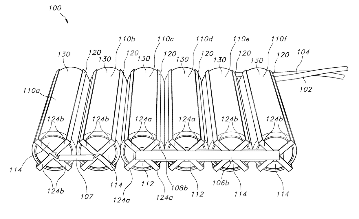
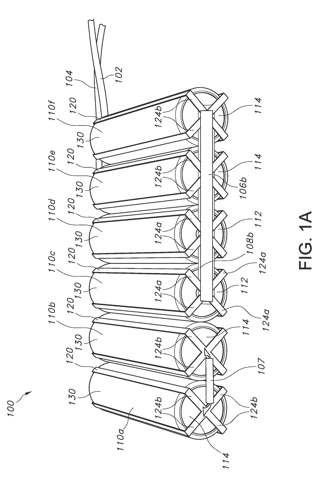
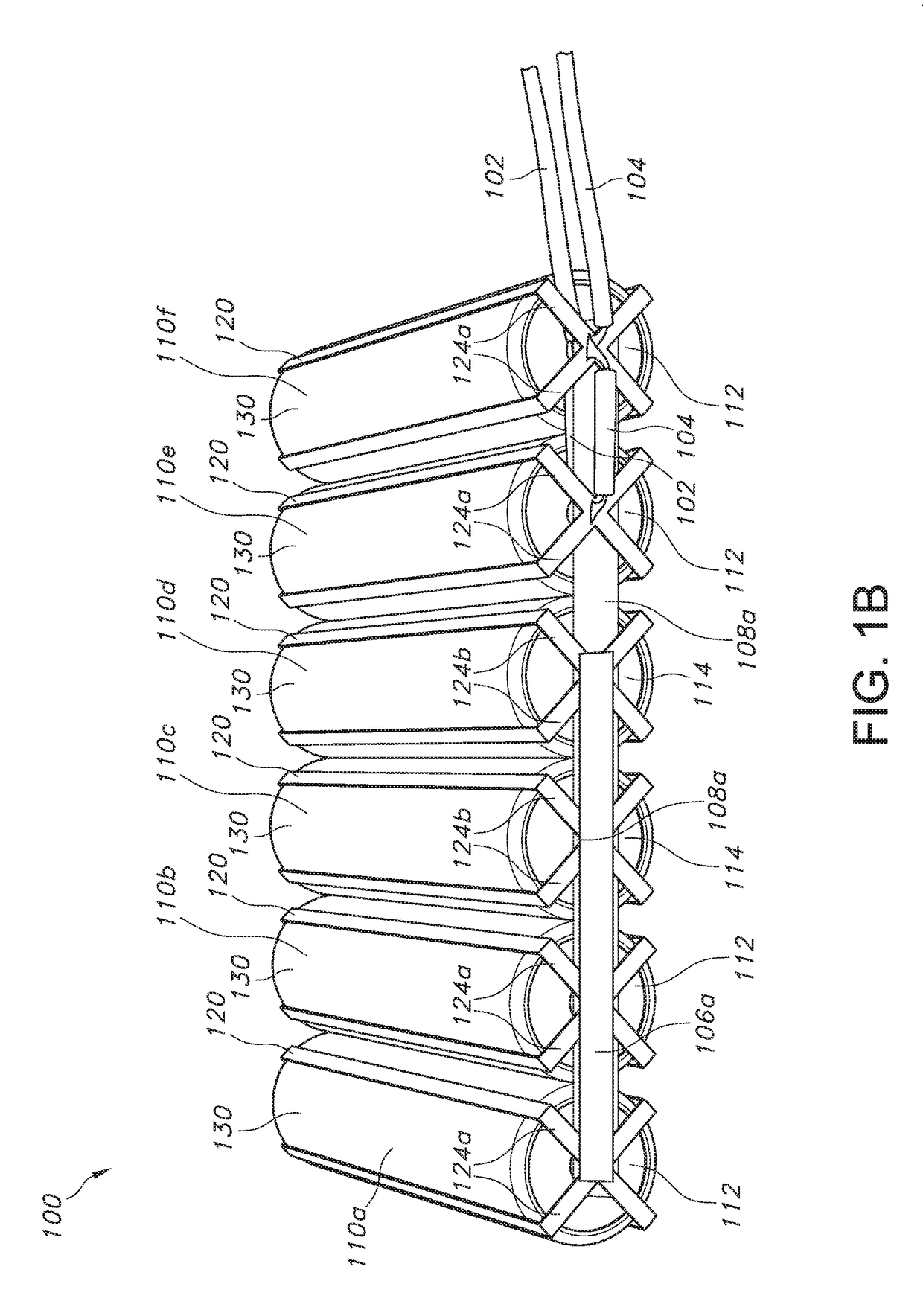
[0029]FIGS. 1A-1C illustrate an example battery pack with reduced magnetic field emission 100 according to the principles of the present disclosure. In some implementations, the battery pack 100 may be configured to reduce and / or eliminate the magnetic field normally generated while electrical current is being drawn from one or more cylindrical-steel electrochemical cells (e.g., AA batteries) by a connected electrical device. In some implementations, the magnetic field generated by the battery pack 100 may be reduced by minimizing or eliminating the loop area of the electrical conductors (e.g., wires or other conductive elements) used to complete the supply path and the return path thereof. In some implementations, the supply path and the return path of a battery pack 100 may be placed into a coaxial arrangement in which only a thin layer of insulating material is positioned therebetween. In this way, the loop area of the electrical conductors is minimized.

[0030]As shown in FIGS. 1A...


PUM

PropertyMeasurementUnit
diameteraaaaaaaaaa
diameteraaaaaaaaaa
magnetic fieldaaaaaaaaaa

Abstract

Implementations of a battery pack with reduced magnetic field emission are provided. In some implementations, the battery pack may be configured to reduce and/or eliminate the magnetic field normally generated while electrical current is being drawn from one or more cylindrical-steel electrochemical cells (e.g., AA batteries) by a connected electrical device. In some implementations, each electrochemical cell of a battery pack may include a conductive sleeve comprised of four conductive strips that are separated from the electrochemical cell by a thin insulating layer of material. In this way, the conductive sleeve provides a return path for electrical current that minimizes the loop area between the electrochemical cell and the conductive sleeve thereof. In some implementations, the four conductive strips of a conductive sleeve may be equally spaced 90 degrees apart and/or positioned longitudinally on a cylindrical-steel electrochemical cell, separated therefrom by the insulating layer of material.

Description

CROSS REFERENCE TO RELATED APPLICATION[0001]This application claims the benefit of U.S. patent application Ser. No. 62 / 449,727, which was filed on Jan. 24, 2017, and is incorporated herein by reference in its entirety.TECHNICAL FIELD[0002]This disclosure relates to implementations of a battery pack with reduced magnetic field emission.BACKGROUND[0003]In general, a magnetic field is generated when electrical current (or current) flows through a wire. Similarly, a magnetic field is generated when current is drawn from a battery by a connected device. If a wire having current flowing therethrough, or a battery having current drawn therefrom, is too close to a device that is sensitive to magnetic fields (e.g., an electronic compass-magnetometer), it will interfere with the proper function (e.g., orientation) of the device.[0004]As an example, the magnetic fields generated by the flow of electrical current are a problem in the field of remotely piloted vehicles and unmanned aerial system...

Claims


Application Information

Patent Timeline
Patent Type & Authority Applications(United States)
IPC IPC(8): H01M2/10H01B1/02H01B3/18H01M2/20H01M50/213H01M50/249H01M50/284H01M50/293H01M50/519H01M50/522
CPCH01M2/1094H01B1/026H01B3/18H01M2/105H01M2/204H01M2220/30Y02E60/10H01M50/213H01M50/24H01M50/293H01M50/522H01M50/249H01M50/519H01M50/284H01M2220/20H01M50/231H01M50/227
Inventor GIESSEL, DAVIDHILDESHEIM, BRUCE
Owner 9013733 CANADA INC
Why Eureka
Try Eureka