System and method for detecting ground position changes

a technology of position change and system, applied in wave based measurement systems, instruments, boundary marks, etc., can solve problems such as the association movement of buildings on the terrain, and achieve the effects of improving the accuracy of the system

Inactive Publication Date: 2018-08-02
SIGNIFY HLDG BV
View PDF6 Cites 7 Cited by
  • Summary
  • Abstract
  • Description
  • Claims
  • Application Information

AI Technical Summary

Benefits of technology

[0032]In a different embodiment, raw positioning and / or movement information is sent to either the central processing unit or proxy device. This ensures that data aggregation and processing can be performed on the raw data of multiple devices improving the accuracy of the system.
[0033]In a different embodiment, the positioning and / or movement system implemented in a lighting device is based on combination of sensor sources. One of those sensor sources is a global positioning system but other sensor sources might be an accelerometer or air pressure sensor. Although the last two sensor sources do not provide global position information, they provide information on position movements derived from changes in acceleration or pressure. This information can be correlated improving accuracy of the system.
[0034]Sensor sources may also include sound sensors and / or wind sensors. Sound sensors may be used in combination with speakers to provide acoustic measurements of the distances between pluralities of sensors (using estimates of the speed of sound, which may in examples be calculated dynamically in response to environmental information). This may enable calibration of sensors or correction of certain errors in GPS position data.
[0035]Wind sensors may improve accuracy in some cases by enabling identification of erroneous movement measurements caused being by wind forces being applied to sensors, rather than terrain movements.

Problems solved by technology

In particular, any geo-location changes in a terrain generally will result in associated movement of buildings on the terrain.

Method used


Image

  • System and method for detecting ground position changes
  • System and method for detecting ground position changes
  • System and method for detecting ground position changes

Examples


Embodiment Construction

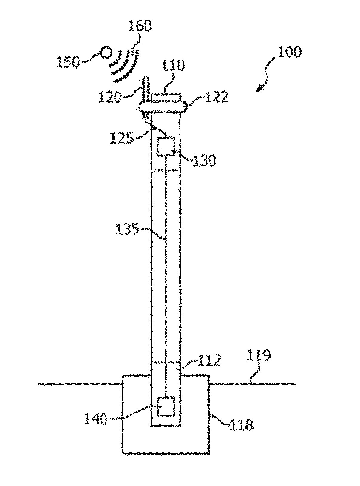
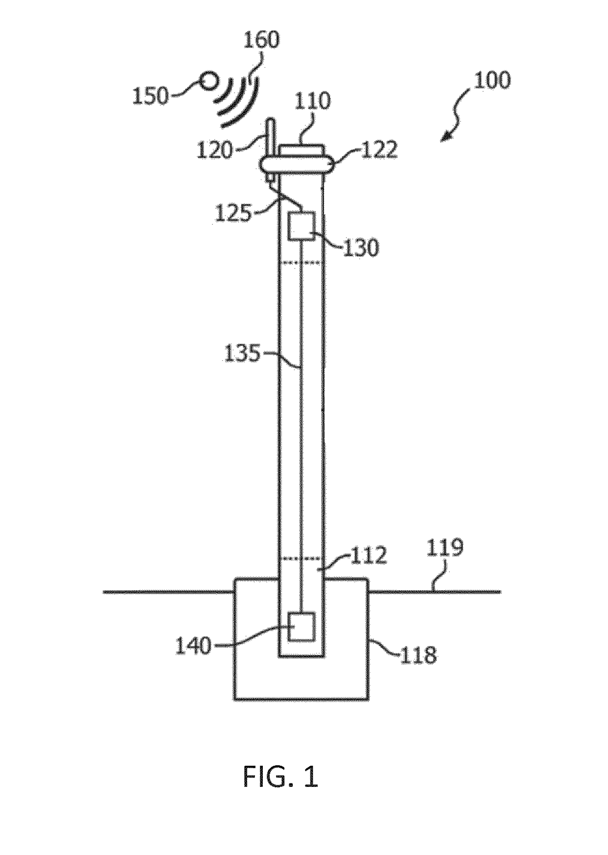
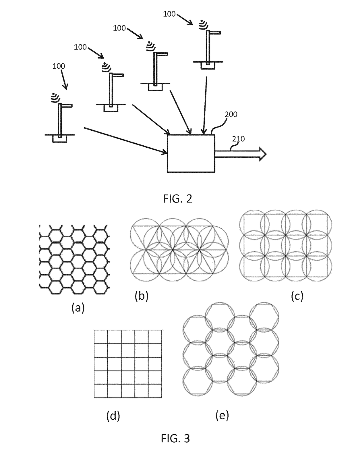
[0046]The invention provides a system for detecting localized ground position changes within an overall area. A plurality of lighting units are each fixed to the ground within the overall area, and each lighting unit comprises a positioning and / or movement detection system and a transmitter for transmitting positioning information to a remote central processing unit. The positioning and / or movement information from the plurality of fixed lighting units is processed to identify local ground position changes. The infrastructure of a networked lighting system in this way enables ground movement information to be determined, for example for detecting ground movement in response to natural events or man-made activities (such as tunneling, building, extraction of natural resources etc.). Preferably, the lighting units include at least an absolute positioning system such as GPS, and then addition sensing systems may provide further information such as acceleration information or other indi...


PUM


Abstract

A system for detecting localized ground position changes makes use of plurality of lighting units, each fixed to the ground. Each lighting unit comprises a positioning system and a transmitter for transmitting positioning information to a remote central processing unit. The positioning information from the plurality of fixed lighting units is processed to identify local ground position changes. The infrastructure of a networked lighting system in this way enables ground information to be determined, for example for detecting ground movement in response to natural events or man-made activities (such as tunneling, building, extraction of natural resources etc.).

Description

FIELD OF THE INVENTION[0001]This invention relates to a system and method for detecting position changes, such as caused by natural events or by human excavations or other activities nearby.BACKGROUND OF THE INVENTION[0002]Geo-location is the identification of the real-world geographic location of an object. Geo-location changes of a terrain or building refer to changes in geographic location of the terrain or building, and such changes may arise as a result of construction work in the surrounding area, natural movement of the ground, or extraction of gas or water or other natural resources that leads to movement of the ground.[0003]Being aware of these position changes is of key importance to ensure safety in cities or reduce maintenance costs of infrastructure. However, there is a lack of accurate geo-location information in respect of buildings. There is also a need for a method to detect such geo-location changes in accurate manner.SUMMARY OF THE INVENTION[0004]The invention is ...

Claims


Application Information

Patent Timeline
Patent Type & Authority Applications(United States)
IPC IPC(8): G01C15/04G01S19/51G01S19/09
CPCG01C15/04G01S19/51G01S19/09G01C15/00G01S19/42G01S19/396
Inventor GARCIA MORCHON, OSCARAOUN, MARCELCANO-FUENTES, MIGUEL
Owner SIGNIFY HLDG BV
Why Eureka
Try Eureka