System for calibration of pressure transducers

a technology for pressure transducers and calibration systems, applied in measurement devices, instruments, scientific instruments, etc., can solve problems such as the error of estimated oil pressure, the impediment to the calibration of pressure transducers at close pressure intervals, and the need for refinements and corrections

Inactive Publication Date: 2005-02-01
COUNCIL OF SCI & IND RES
View PDF7 Cites 15 Cited by
  • Summary
  • Abstract
  • Description
  • Claims
  • Application Information

AI Technical Summary

Benefits of technology

Still another object of the present invention is to provide a system that facilitates study of temperature-dependence sensitivity of pressure transducers by locating the said pressure transducers together with their common mounting means in a medium whose temperature can be maintained constant at a given desired value during a given set of input pressure values, and altered to a different constant temperature value during a subsequent set of input pressure values as required during calibration.
3. Improving the calibration accuracy by providing a means to circumvent the temperature sensitivity of the pressure-standard against which the pressure transducers are calibrated. Amongst the currently available pressure standards, those that provide the finest pressure resolution are the quartz pressure transducers that are operated at the optimum constant ambient temperature as reported by J. M. Paros [in “Digital Pressure Transducer”, U.S. Pat. No. 4,455,874(1984)], and further reported by R. B. Wearn, Jr., and J. M. Paros [in “Measurements of dead weight tester performance using high resolution quartz crystal pressure transducers”, Instrument Society of America, 8 pp, [(1988)]. The calibration accuracy of the system of the present invention is improved by locating the quartz pressure transducer (pressure-standard) in a fluid medium (water) whose temperature can be maintained constant at the optimum temperature at which it provides the best results.

Problems solved by technology

The disadvantage of this arrangement is the error involved in the estimated oil-pressure due to frictional resistance offered to the motion of the plunger in the cylinder.
Another drawback is that the number of calibrated weights available with a dead-weight tester is limited, thereby impeding the calibration of the pressure transducer at close pressure intervals.
A drawback of this methodology is that a number of refinements and corrections are necessary to achieve highly accurate results.
Another drawback is that corrections are needed for temperature effects on areas of piston and cylinder, air and pressure-medium buoyancy effects, local gravity conditions, and height differences between the lower end of the piston and the reference point for the pressure transducer being calibrated.
Further, as the piston assembly itself has weight, conventional dead-weight gages are not capable of measuring pressures lower than the piston weight / area ratio.
However, a disadvantage of this device is that it becomes unwieldy at high pressures because of the long liquid columns involved.
Additional sources of error are found in the non-verticality of the tubes and the difficulty in reading h because of the meniscus formed by capillarity.
A disadvantage of this system, however, is that its calibration accuracy is limited by the temnperature-sensitivity of the pressure-standard against which the pressure calibration is performed.
Another limitation of this system is that it does not provide a means to study the temperature-dependence of the pressure transducers being calibrated.
Yet another disadvantage of this system is that the number of pressure transducers that can be calibrated simultaneously is limited to two.

Method used


Image

  • System for calibration of pressure transducers
  • System for calibration of pressure transducers
  • System for calibration of pressure transducers

Examples


Embodiment Construction

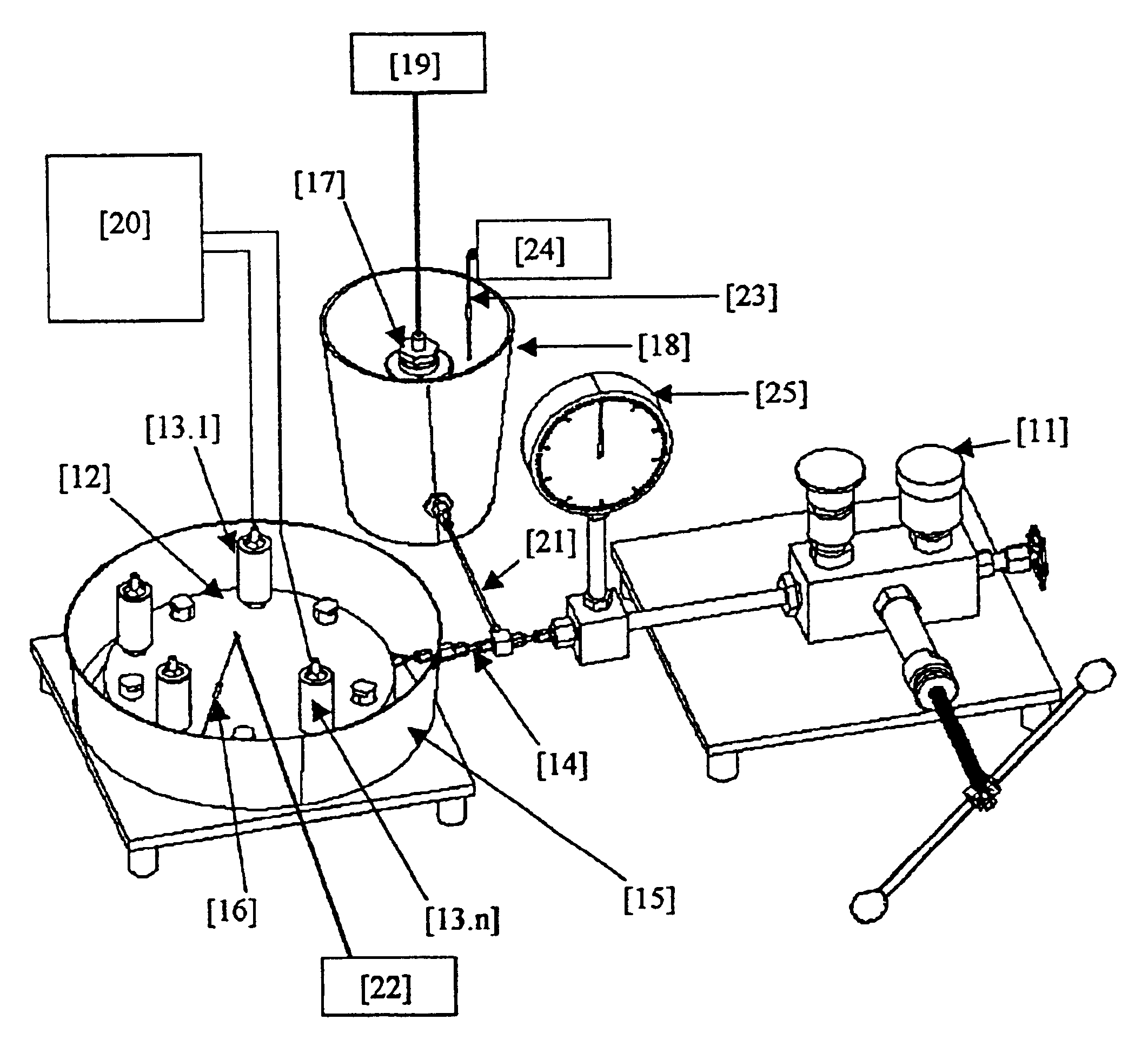
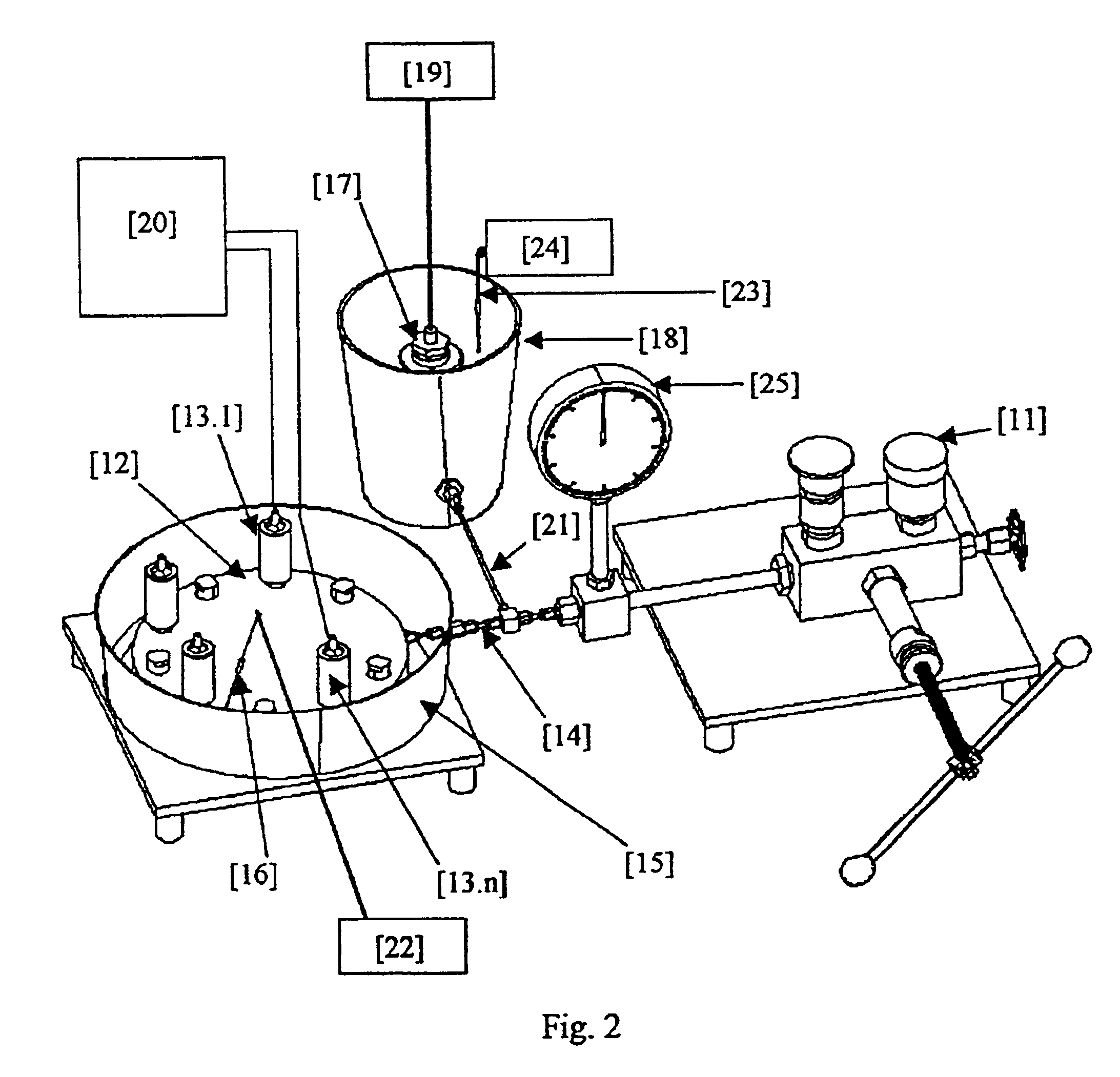
Accordingly, the present invention provides a system for calibrating plurality of pressure transducers, said system comprising plurality of pressure transducers (13.1 to 13.n) mounted on a mounting means (12) which receives pressure input from a pressure source (11) via a hollow pipe (14) and distributes the pressure evenly to all the pressure transducers, said plurality of pressure transducers are mounted on the mounting means and placed inside a vessel (15) so as to vary the temperature of the pressure transducers, said pressure source is also connected to a standard pressure transducer (17) whose temperature is maintained at the same level as that of pressure transducers(13.1 to 13.n).

In an embodiment of the present invention, the means for mounting (12) the pressure transducers (13.1 to 13.n) comprises of a cylindrical body having an input channel (30) connected to the hollow cylinder (14) via a link 31 and an adapter (32) to receive the pressure, said cylindrical body is cast w...


PUM

PropertyMeasurementUnit
pressureaaaaaaaaaa
pressureaaaaaaaaaa
temperatureaaaaaaaaaa

Abstract

The present invention relates to system for calibrating plurality of pressure transducers, said system comprising plurality of pressure transducers (13.1 to 13.n) mounted on a mounting means (12) which receives pressure input from a pressure source (11) via a hollow pipe (14) and distributes the pressure evenly to all the pressure transducers, said plurality of pressure transducers are mounted on the mounting means and placed inside a vessel (15) as to vary the temperature of the pressure transducers, said pressure source is also connected to a standard pressure transducer (17) whose temperature is maintained at the same level as that of pressure transducers (13.1 to 13.n).

Description

FIELD OF THE INVENTIONThe present invention relates to a system for calibrating plurality of pressure transducers, said system comprising plurality of pressure transducers (13.1 to 13.n). More particularly, the present invention relates to a system which facilitates the study of temperature-dependence sensitivity of a plurality of pressure transducers, said system improves the calibration accuracy by providing a means to circumvent the temperature sensitivity of a standard pressure transducer against which the pressure transducers are calibrated. The system also improves the calibration resolution by providing a means to calibrate the pressure transducer at close pressure intervals said system also minimizes the stabilization time for the pressure input at the transducers and thereby reducing the time duration required for calibration.BACKGROUND OF THE INVENTIONHitherto known systems for calibration of pressure transducers [P. N. Modi and S. M. Seth, “Fluid Pressure and Its Measurem...

Claims


Application Information

Patent Timeline
Patent Type & Authority Patents(United States)
IPC IPC(8): G01L27/00
CPCG01L27/005G01L27/00
Inventor JOSEPH, ANTONYKUMAR, VIJAYPRABHUDESAI, SHIVANANDMEHRA, PRAKASHDESA, EHRLICHNAGVEKAR, SUREKHA MAHESH
Owner COUNCIL OF SCI & IND RES
Why Eureka
Try Eureka