Eureka AIR delivers breakthrough ideas for toughest innovation challenges, trusted by R&D personnel around the world.

Positioning device and positioning method

Active Publication Date: 2018-08-02
FURUNO ELECTRIC CO LTD
View PDF4 Cites 0 Cited by
  • Summary
  • Abstract
  • Description
  • Claims
  • Application Information

AI Technical Summary

Benefits of technology

The present patent provides a positioning device that uses triple phase differences to accurately position itself. The device detects carrier phases from multiple positioning satellites and calculates the triple phase difference, which is the difference between two double phase differences. This value is then added over time to account for any changes in the carrier phase. By using this approach, the device can accurately position itself relative to the satellites without needing to calculate an integer bias. Additionally, the device can set weights for each combination of satellites based on its acquisition time, which helps to prioritize the importance of the triple phase difference in the positioning process.

Problems solved by technology

Therefore, the observation value for the relative positioning may easily be acquired, and a situation in which the relative positioning cannot be performed may become difficult to occur.

Method used


Image

  • Positioning device and positioning method
  • Positioning device and positioning method
  • Positioning device and positioning method

Examples


Embodiment Construction

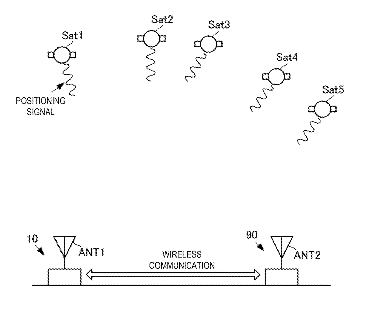
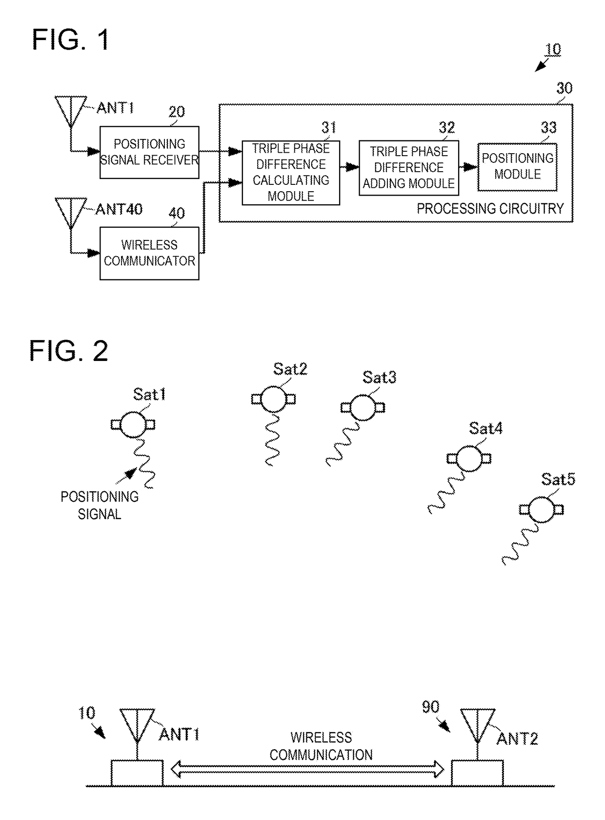
[0020]A positioning device, a positioning method, and a positioning program according to one embodiment of the present disclosure will be described with reference to the drawings. FIG. 1 is a block diagram of the positioning device according to the embodiment of the present disclosure. FIG. 2 is a configuration diagram of a positioning system according to the embodiment of the present disclosure.

[0021]As illustrated in FIG. 1, the positioning device 10 may include a positioning signal receiver 20, processing circuitry 30, a wireless communicator 40, an antenna ANT1, and an antenna ANT40. The processing circuitry 30 may include a triple phase difference calculating module 31, a triple phase difference adding module 32, and a positioning module 33. As illustrated in FIG. 2, the positioning system which includes this positioning device 10 may include the positioning device 10, a positioning device 90 of a base station, and a plurality of positioning satellites Sat1, Sat2, Sat3, Sat4 an...


PUM


Abstract

The purpose is to achieve accurate positioning without calculating an integer bias. A positioning device may include a positioning signal receiver, a triple phase difference calculating module, a triple phase difference adding module, and a positioning module. The positioning signal receiver may detect carrier phases of positioning signals from a plurality of positioning satellites. The triple phase difference calculating module may calculate a triple phase difference based on the carrier phases. The triple phase difference adding module may add the plurality of triple phase differences calculated in different periods. The positioning module may perform relative positioning using an added value of the triple phase differences as an observation value.

Description

TECHNICAL FIELD[0001]The present disclosure relates to a positioning device, a positioning method, and a positioning program which perform relative positioning.BACKGROUND ART[0002]Conventionally, various positioning devices have been devised for performing positioning using positioning signals of a GNSS system, such as a GPS.[0003]For example, a positioning device described in Patent Document 1 attempts to achieve highly accurate positioning by performing relative positioning. The positioning device described in Patent Document 1 performs the relative positioning using a double phase difference of a carrier phase and a double phase difference of a code pseudo distance.REFERENCE DOCUMENT OF CONVENTIONAL ARTPatent Document[0004]Patent Document 1 JP2000-193733ADESCRIPTION OF THE DISCLOSUREProblems to be Solved by the Disclosure[0005]However, when the double phase difference of the carrier phase as described in Patent Document 1 is used, an integer bias is required to be calculated. Sin...

Claims


Application Information

Patent Timeline
IPC IPC(8): G01S19/43G01S19/51
CPCG01S19/43G01S19/51G01S19/41
Inventor TORII, HAYATO
Owner FURUNO ELECTRIC CO LTD
Why Eureka
Eureka Blog
Learn More