
Eureka
For R&D, Eureka makes reading and utilizing patents & technical documents easy.
Eureka AIR
Designed for self-driven R&D workflows. Generate viable solutions, solve complex R&D challenges, empower your innovation with AI.

Eureka Materials
Designed for material experts only. Revolutionize your material R&D, from search, analyze, to developing new materials.

TechResearch
Generate reliable direction feasibility study reports for your R&D in just a few steps.

TechSeek
Discover and master advanced knowledge NOW. Basics, ideas, possibilities, all at once.

TechMind
As an expert in R&D Theories, TechMind can generates customized viable solutions instantly.

TechRisk
Analyze your overall solution with one click, know your potential R&D risks in advance.

TechMonitor
Get weekly tech updates, stay abreast of the latest tech innovations and key insights.
Road greening trimming device
A pruning device and road technology, applied in watering devices, chemical instruments and methods, cutting tools, etc., can solve the problems of inaccurate positioning of green belts, height difference of green shrub walls, and large amount of manual labor, so as to protect the environment, Low labor intensity and the effect of reducing labor force
- Summary
- Abstract
- Description
- Claims
- Application Information
AI Technical Summary
Problems solved by technology
Method used
Image

Examples
Embodiment 1
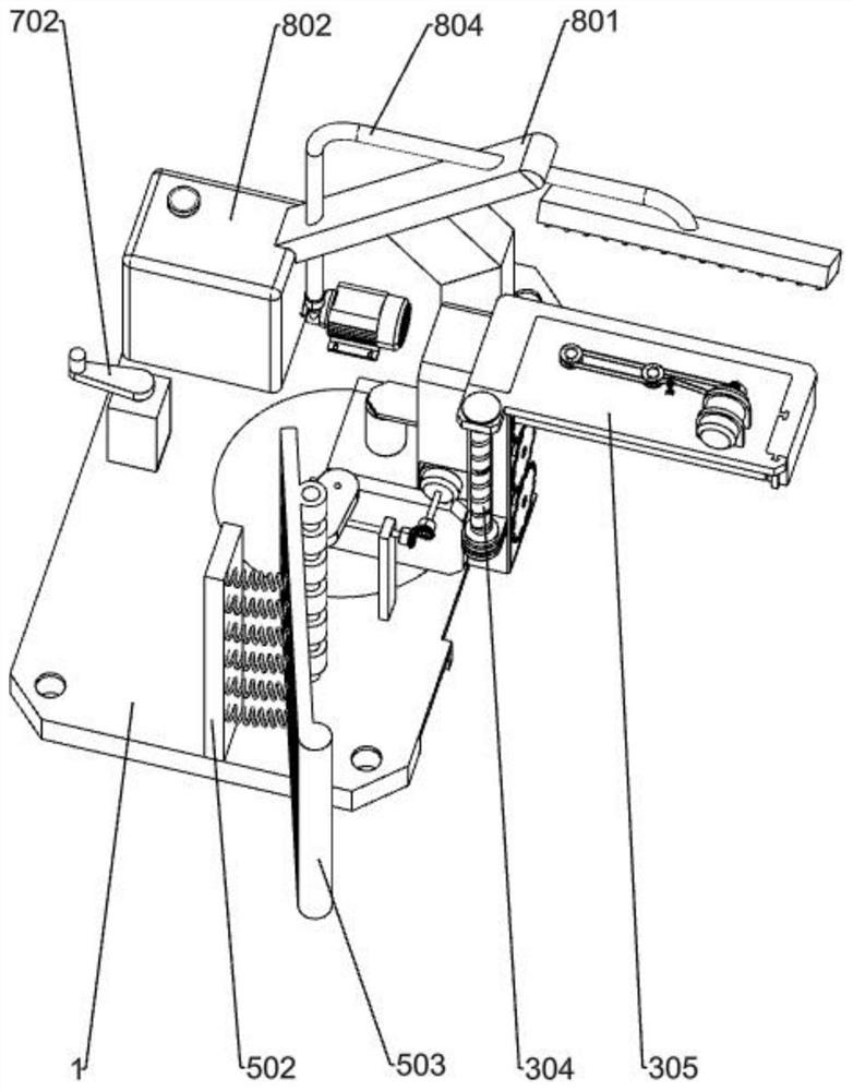
[0035] Specific implementation methods, such as Figure 1-12 As shown, it includes a bottom frame 1, a side trimming device and a top trimming device. A circular groove is provided at the middle right of the bottom frame 1, and some components of the side trimming device are fixedly connected to the upper right side of the bottom frame 1, and the top Some components of the trimming device are fixedly connected to the upper right side of the side trimming device.
[0036] When trimming the green shrub wall in the middle of the road, the construction personnel need to first install the green trimming device on the work vehicle through the chassis 1, and when reaching the green shrub wall in the middle of the road that needs to be trimmed, start the green trimming device at this time, and drive the operation The car moves forward at a constant speed, and the side trimming device and the top trimming device begin to trim the green shrub wall in the middle of the road.
Embodiment 2
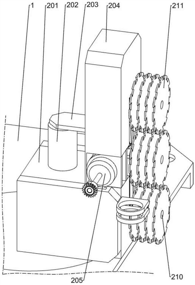
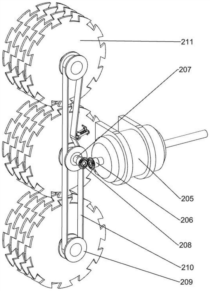
[0038] When used, such as Figure 2-3 As shown, the side trimming device has a fixed seat 201, a telescopic cylinder 202, a horizontal plate 203, a first fixed frame 204, a first motor 205, a first bevel gear 206, a first rotating shaft 207, a second bevel gear 208, a first The synchronous wheel 209, the first belt 210 and the first blade group 211, the fixed seat 201 is fixedly connected to the upper right side of the chassis 1, the telescopic cylinder 202 is fixedly connected to the upper part of the fixed seat 201, and the left side of the horizontal plate 203 is fixedly connected to the telescopic cylinder 202 On the output shaft, the right side of the horizontal plate 203 is fixedly connected to the first fixed frame 204, the first fixed frame 204 is slidably connected to the fixed seat 201 through the guide grooves provided on the front and rear sides, and the first motor 205 is a biaxial motor , the first motor 205 is fixedly connected in the first fixed frame 204, the ...
Embodiment 3
[0041] When used, such as Figure 4-5 As shown, the top trimming device has a second fixed mount 301, a third fixed mount 302, a second motor 303, a lead screw slide rail 304, a fourth fixed mount 305, a fifth fixed mount 306, a third motor 307, a third awl Gear 308, the second rotating shaft 309, the fourth bevel gear 310, the second synchronous wheel 311, the second belt 312 and the second blade group 313, the second fixed mount 301 is fixedly connected on the first fixed mount 204, the third fixed mount 302 is fixedly connected on the second fixed frame 301, the second motor 303 is fixedly connected in the third fixed frame 302, one end of the lead screw slide rail 304 is connected to the output shaft of the second motor 303 in rotation, and the other end of the lead screw slide rail 304 rotates Connect the second fixed frame 301, guide grooves are provided on both sides of the fourth fixed frame 305, the fourth fixed frame 305 is slidingly connected with the second fixed f...
PUM
 Abstract
Description
Claims
Application Information
 - R&D Engineer
- R&D Manager
- IP Professional
- Industry Leading Data Capabilities
- Powerful AI technology
- Patent DNA Extraction
Browse by: Latest US Patents, China's latest patents, Technical Efficacy Thesaurus, Application Domain, Technology Topic, Popular Technical Reports.
© 2024 PatSnap. All rights reserved.Legal|Privacy policy|Modern Slavery Act Transparency Statement|Sitemap|About US| Contact US: help@patsnap.com