Method for forming image and protective layer and apparatus therefor

Active Publication Date: 2018-08-09
DAI NIPPON PRINTING CO LTD
View PDF5 Cites 1 Cited by
  • Summary
  • Abstract
  • Description
  • Claims
  • Application Information

AI Technical Summary

Benefits of technology

The present invention relates to a method to enhance the smoothness and glossiness of images and protective layers formed on transfer receiving materials. The method involves shifting the relative positions of the thermal head and the transfer receiving material in parallel with the main scanning direction. This improves the quality and clarity of the images and protective layers, resulting in better quality finished products.

Problems solved by technology

This causes the occurrence of irregularities on the surface of the image receiving sheet, which is the transfer receiving material, thereby decreasing the smoothness and glossiness of the resulting image surface.
Therefore, there is a risk of an increase in the size of the printer and an increase in the production cost.

Method used


Image

  • Method for forming image and protective layer and apparatus therefor
  • Method for forming image and protective layer and apparatus therefor
  • Method for forming image and protective layer and apparatus therefor

Examples


example 1

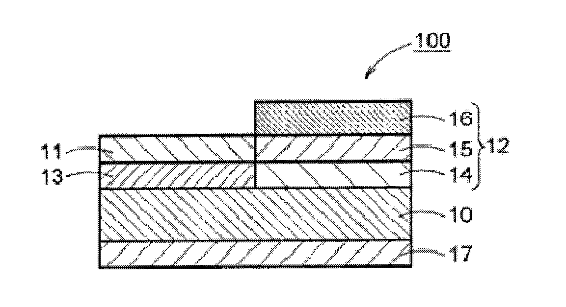
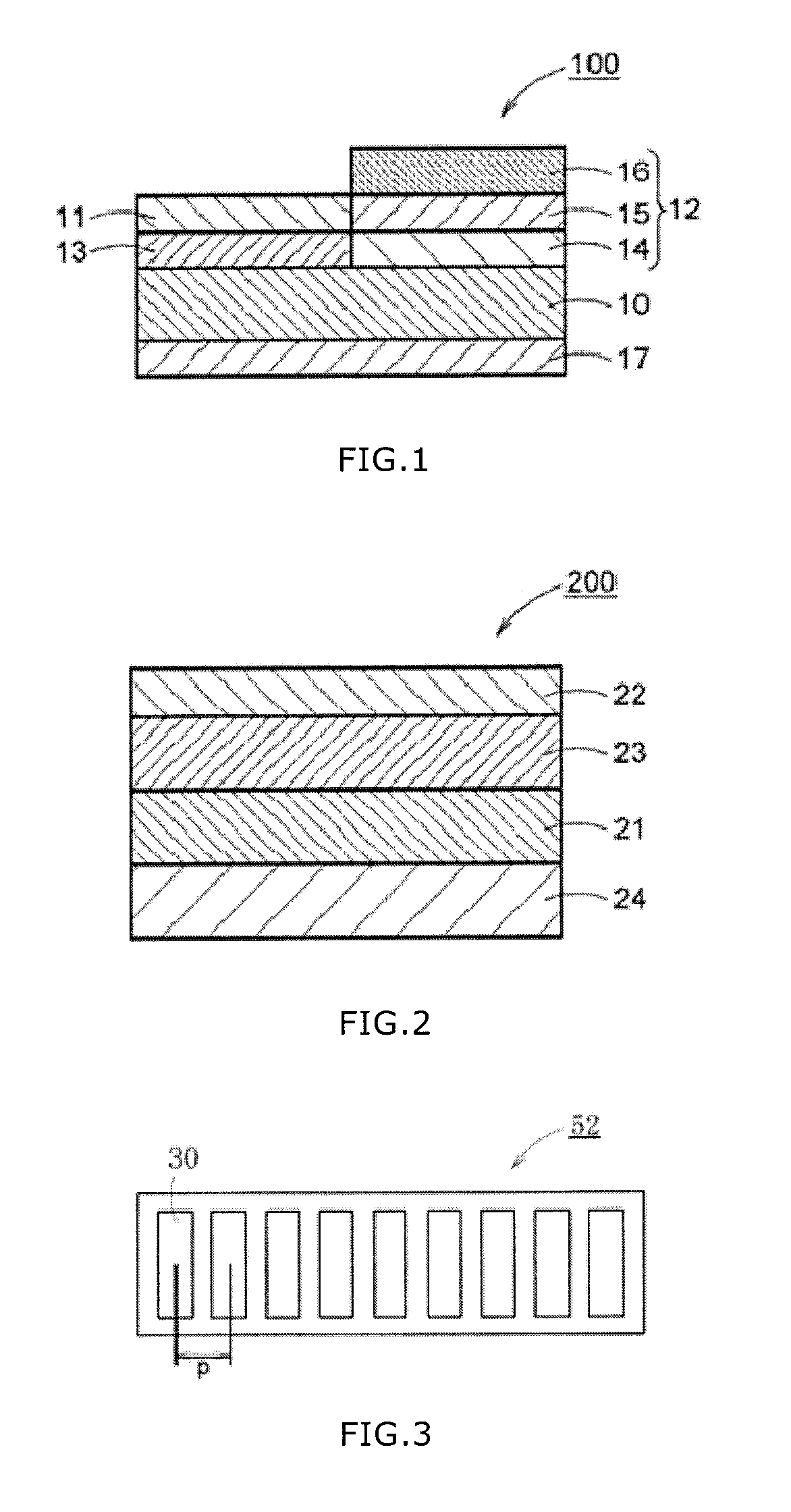
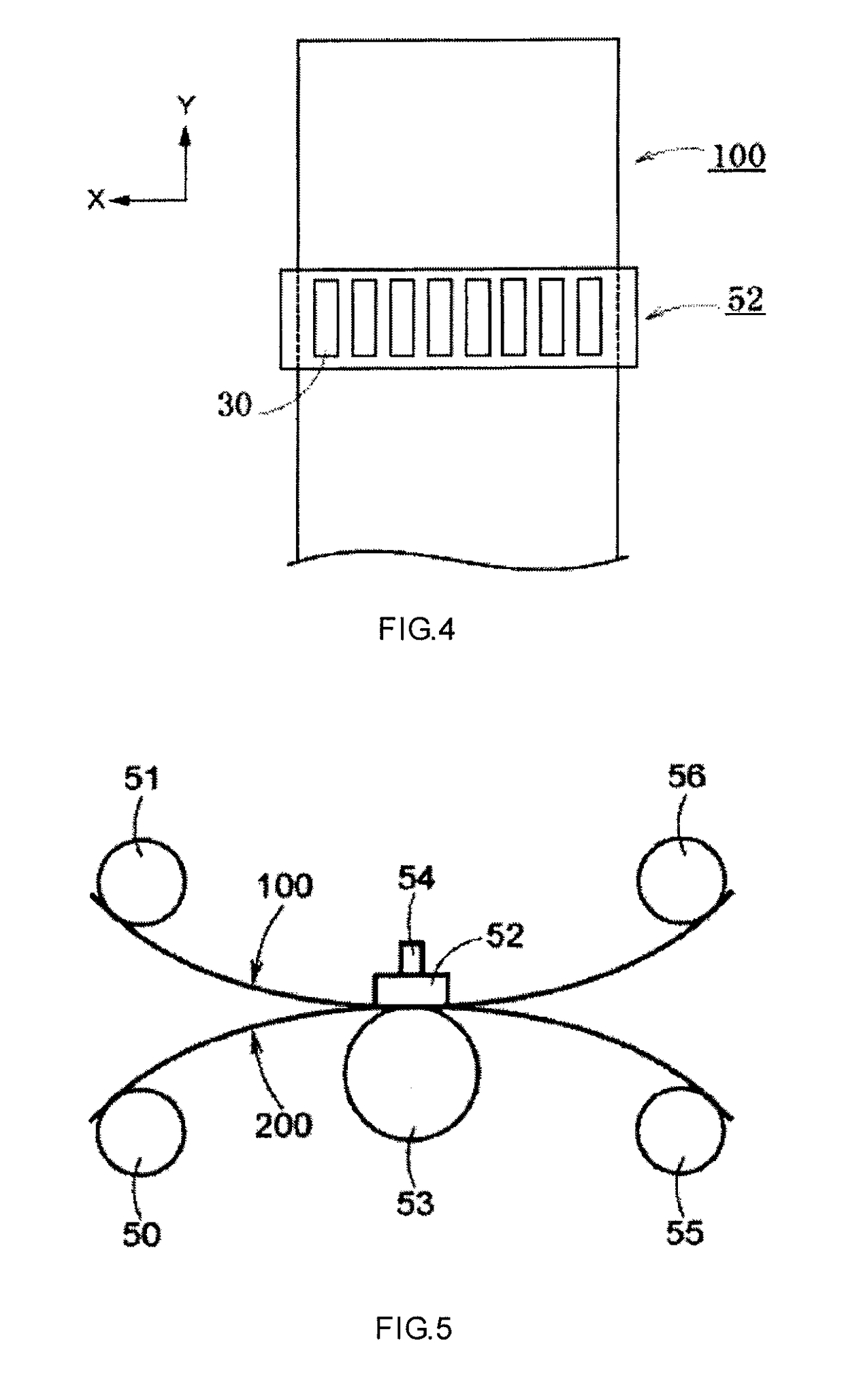
[0124]In a thermal printer 500 (gradation control system; a multi pulse system in which the number of divided pulses, obtained by dividing one line period into 256 pulses or the like, can be varied from 0 to 255) shown in FIG. 5, the thermal transfer sheet 100 was fed from the supply roll 51, and the transfer receiving material 200 was fed from the supply roller 50, and both were supplied between the thermal head 52 and the platen roller 53. The thermal head 52 and the platen roller 53 had been disposed so as to be pressable against each other, with the color material layers (not shown) and the transferable protective layer (namely, the peeling layer, the primer layer and the adhesive layer) of the thermal transfer sheet 100, and the receiving layer of the transfer receiving material 200, being layered and sandwiched therebetween. The thermal head (trade name: KEE-57-12GAN2-STA; manufactured by KYOCERA Corporation) used was one including a plurality of heat generating portions exten...

example 2

[0129]The same procedure as in Example 1 was repeated, except that the stepping motor 54 had been set so as to move the position of the thermal head 52 by 50 μm (about 0.6 times the dot pitch p) in the direction substantially in parallel with the main scanning direction, to form a protective layer on the image.

example 3

[0130]The same procedure as in Example 1 was repeated, except that the stepping motor 54 had been set so as to move the position of the thermal head 52 by 25 μm (about 0.3 times the dot pitch p) in the direction substantially in parallel with the main scanning direction, to form a protective layer on the image.


PUM

PropertyMeasurementUnit
Distanceaaaaaaaaaa

Abstract

A method for forming an image and a protective layer on a transfer receiving material, by thermal transfer, including supplying a thermal transfer sheet between a thermal head of a thermal printer and a platen roller, wherein the thermal transfer sheet includes color material layers and a transferable protective layer arranged in a face serial manner, and wherein the thermal head includes heat generating portions arranged substantially in parallel with each other; thermally transferring the color material layers to form an image on the transfer receiving material; thermally transferring the transferable protective layer to form a protective layer on the transfer receiving material; and shifting the relative positions of the thermal head and the transfer receiving material with respect to each other, in a direction substantially in parallel with a main scanning direction, after transferring the color material layers at least once.

Description

BACKGROUND OF THE INVENTIONField of the Invention[0001]The present invention relates to a method for forming an image and a protective layer, and an apparatus therefor.Background Art[0002]Conventionally, a method is known in which image formation is performed using a thermal transfer sheet including color material layers which contain color materials, such as dyes, and by transferring the color materials onto an image receiving sheet. In such an image forming method, the formation of an image is carried out by: layering the thermal transfer sheet, and the image receiving sheet, which is a transfer receiving material; applying thermal energy provided by a heat source referred to as a thermal head to the thermal transfer sheet; and transferring the color materials of the thermal transfer sheet onto the image receiving sheet, which is the transfer receiving material. The image formation carried out by such a thermal transfer method allows for a gray scale adjustment by controlling the ...

Claims


Application Information

Patent Timeline
IPC IPC(8): B41M7/00B41J2/325
CPCB41M7/0054B41J2/325B41J2202/31B41M5/382B41J2/32B41M7/0027
Inventor YABE, SUGURUSEKIGUCHI, HIDEKI
Owner DAI NIPPON PRINTING CO LTD
Why Eureka
Try Eureka