
Pulsing laser spot tracking and decoding

Active Publication Date: 2018-08-09
SENSORS UNLTD
View PDF1 Cites 0 Cited by
  • Summary
  • Abstract
  • Description
  • Claims
  • Application Information

AI Technical Summary

Benefits of technology

The patent describes a method for detecting a laser's pulse repetition interval (PRI) and improving the sampling precision of certain parts of an image. This allows for more precise detection of the laser's time of arrival (TOA) without consuming additional power and is useful for applications such as lidar imaging. The method can improve the resolution of the image by about 22 times for the same data bandwidth.

Problems solved by technology

Currently available methods of laser spot tracking and frequency decoding are not suited to low power implementations.
Accurate tracking and frequency measurement requires an image sensor which runs at very high speed and, as a result, the electronics require high operating power which limits the run time of handheld, battery powered devices.

Method used


Image

  • Pulsing laser spot tracking and decoding
  • Pulsing laser spot tracking and decoding
  • Pulsing laser spot tracking and decoding

Examples


Embodiment Construction

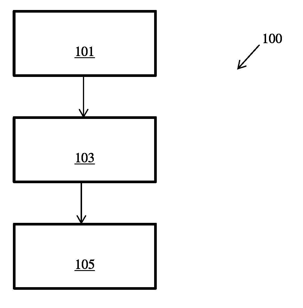
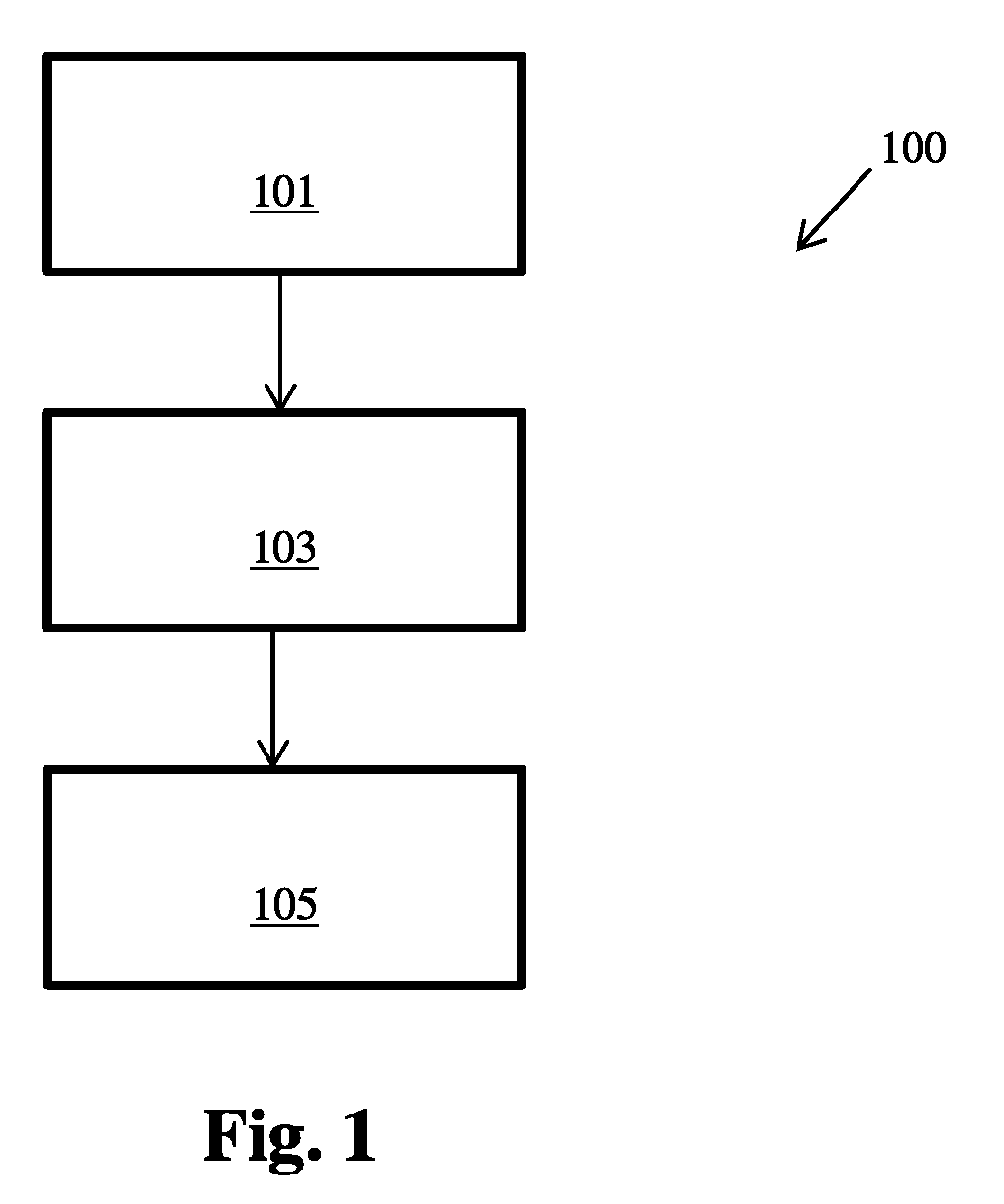
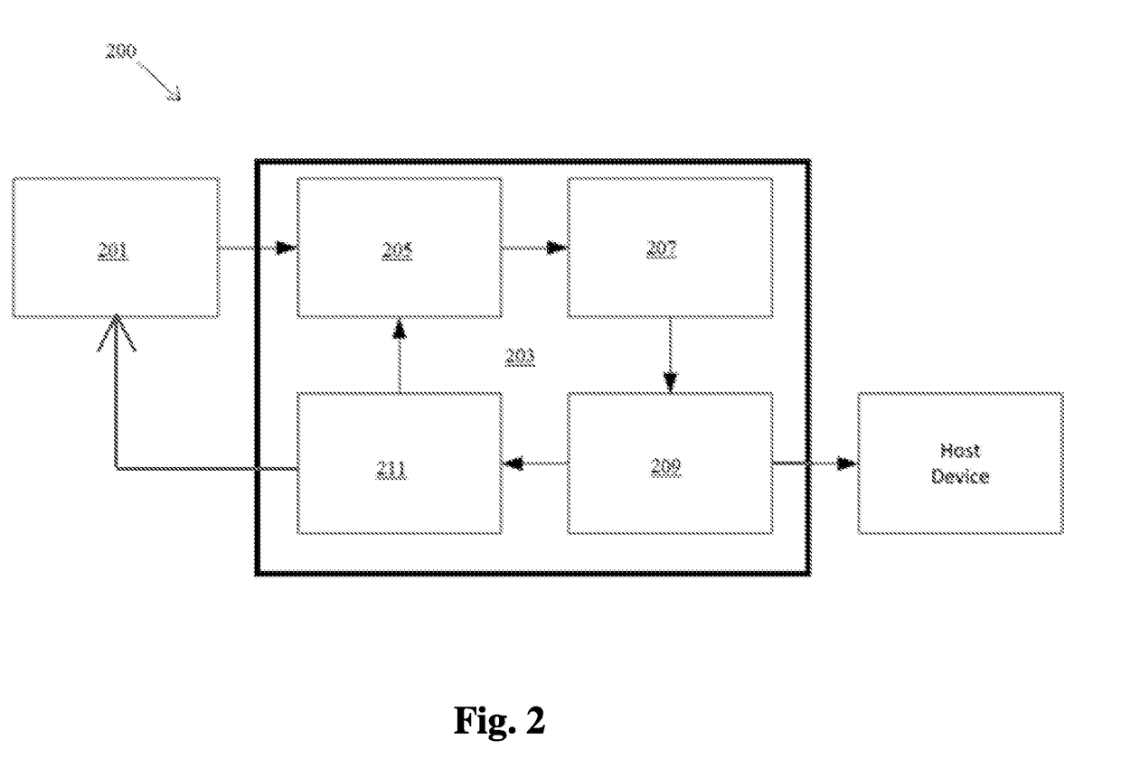
[0018]Reference will now be made to the drawings wherein like reference numerals identify similar structural features or aspects of the subject disclosure. For purposes of explanation and illustration, and not limitation, an illustrative view of an embodiment of a method in accordance with the disclosure is shown in FIG. 1 and is designated generally by reference character 100. Other embodiments and / or aspects of this disclosure are shown in FIGS. 2 and 3. The systems and methods described herein can be used to reduce energy consumption in detecting and / or decoding pulsed lasers, for example. Any other suitable use is contemplated herein.

[0019]Referring to FIG. 1, a method 100 is shown. The method 100 can be embodied in any suitable computer executable instructions (e.g., code) and stored on a non-transitory computer readable medium.

[0020]The method 100 can include locating (e.g., at block 101) a pulsing laser on an imaging array. The method 100 also includes defining (e.g., at bloc...


PUM


Abstract

A non-transitory computer readable medium including computer executable instructions for performing a method that includes locating a pulsing laser on an imaging array, defining a sub-region array smaller than the imaging array based on a location of the located pulsing laser such that the pulsing laser is at least partly within the sub-region, and sampling the sub-region array at a sub-region sampling rate that is higher than a remainder region sampling rate.

Description

BACKGROUND1. Field[0001]The present disclosure relates to laser spot tracking, more specifically to frequency decoding.2. Description of Related Art[0002]Currently available methods of laser spot tracking and frequency decoding are not suited to low power implementations. Accurate tracking and frequency measurement requires an image sensor which runs at very high speed and, as a result, the electronics require high operating power which limits the run time of handheld, battery powered devices.[0003]Such conventional methods and systems have generally been considered satisfactory for their intended purpose. However, there is still a need in the art for improved laser spot tracking and frequency decoding systems. The present disclosure provides a solution for this need.SUMMARY[0004]A non-transitory computer readable medium including computer executable instructions for performing a method that includes locating a pulsing laser on an imaging array, defining a sub-region array smaller t...

Claims


Application Information

Patent Timeline
IPC IPC(8): G01S7/486G01J1/42G01S7/4863G01S17/10
CPCG01S7/4863G01J2001/4238G01J1/42G01S17/10F41G7/2293
Inventor ECKHARDT, ANDREWSUKHTANKAR, SATYEN
Owner SENSORS UNLTD
Learn More