Plain milling tool for rounded corners

A face milling cutter, milling cutter technology, applied in milling cutters, milling cutting inserts, milling machine equipment and other directions, can solve the problems of high processing efficiency, low processing efficiency, rough arc surface, etc., and achieve high processing efficiency and fine precision. Effect

Inactive Publication Date: 2016-12-14
TIANJIN HUATIAN CENTURY MACHINERY
View PDF10 Cites 1 Cited by
  • Summary
  • Abstract
  • Description
  • Claims
  • Application Information

AI Technical Summary

Problems solved by technology

In the process of machining mechanical parts, it is often necessary to process R angles of different sizes. The face milling cutter in the prior art is usually a milling cutter with a three-sided edge. The three-sided edge milling cutter is usually used to process grooves, step surfaces, etc. When the R angle is used, only larger R angles can be processed, and the processing efficiency is low. Applicable, so in order to overcome the above problems, the present invention designs a new type of R-angle face milling cutter, which can process R-angles of different sizes, and has high processing efficiency, and the processed arc surface is more detailed

Method used


Image

  • Plain milling tool for rounded corners
  • Plain milling tool for rounded corners
  • Plain milling tool for rounded corners

Examples


Embodiment Construction

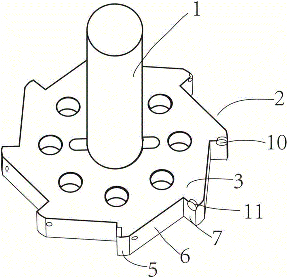
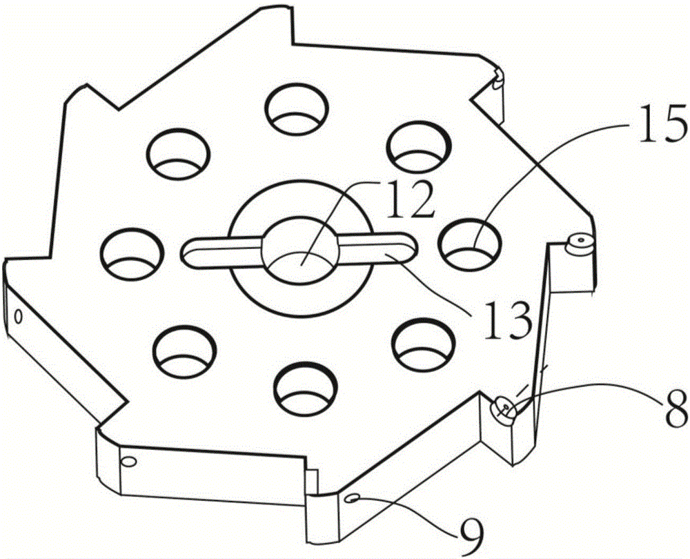
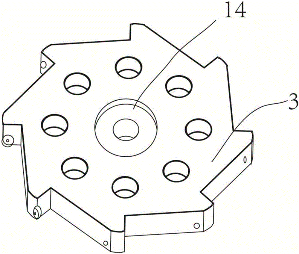
[0026] The technical solutions of the present invention will be clearly and completely described below in conjunction with the accompanying drawings. Apparently, the described embodiments are some of the embodiments of the present invention, but not all of them. Based on the embodiments of the present invention, all other embodiments obtained by persons of ordinary skill in the art without making creative efforts belong to the protection scope of the present invention.

[0027] In the description of the present invention, it should be noted that the terms "center", "upper", "lower", "left", "right", "vertical", "horizontal", "inner", "outer" etc. The indicated orientation or positional relationship is based on the orientation or positional relationship shown in the drawings, and is only for the convenience of describing the present invention and simplifying the description, rather than indicating or implying that the referred device or element must have a specific orientation, ...


PUM


Abstract

A plain milling tool for rounded corners comprises a tool handle and a tool bit. The plain milling tool for rounded corners is characterized in that the tool bit is a tooth-shaped tool bit and is provided with a plurality of tool rests; the tool rests are located at the junctions of vertical planes and inclined planes, and the tool rests are in an incomplete circular truncated cone shape; the tool rests are provided with threaded holes extending in the direction of a taper, and the threaded holes are coaxial with the tool rests; each tool rest is fixedly provided with a milling tool body which is in a circular truncated cone shape; the height of each milling tool body in the circular truncated cone shape is coincident with the feeding length of the corresponding tool rest; a connection hole is formed in the center portion of the tool bit; the front end face of the tool bit is provided with a clamping groove perpendicular to the connection hole, and the clamping groove is in a rounded rectangle shape; and the rear end face of the tool bit is provided with a screw slot which is concentric and coaxial with the connection hole. According to the designed milling tool, by the adoption of the milling tool bodies in the circular truncated cone shape and the tooth-shaped tool bit, the tool bit can directly machine out rounded corners when the tool handle is driven by a motor to rotate at a high speed, round corners of different dimensions can be machined, and the machining efficiency and precision are high.

Description

technical field [0001] The invention belongs to the field of mechanical processing tools, and in particular relates to a milling cutter, in particular to a high-precision R-angle plane milling cutter. Background technique [0002] The cutting tool is the main tool for processing the surface of the workpiece. During use, it is necessary to select the cutting tool corresponding to the size requirement according to different processing requirements. In the process of machining mechanical parts, it is often necessary to process R angles of different sizes. The face milling cutter in the prior art is usually a milling cutter with a three-sided edge. The three-sided edge milling cutter is usually used to process grooves, step surfaces, etc. When the R angle is used, only larger R angles can be processed, and the processing efficiency is low. Applicable, so in order to overcome the above problems, the present invention designs a new type of R-angle face milling cutter, which can p...

Claims


Application Information

Patent Timeline
Patent Type & Authority Applications(China)
IPC IPC(8): B23C5/12B23C5/20
CPCB23C5/12B23C5/20B23C2200/045
Inventor 丁桐
Owner TIANJIN HUATIAN CENTURY MACHINERY
Why Eureka
Try Eureka