Imaging device and control method therefor

Active Publication Date: 2018-08-09
FUJIFILM CORP
View PDF2 Cites 0 Cited by
  • Summary
  • Abstract
  • Description
  • Claims
  • Application Information

AI Technical Summary

Benefits of technology

The present invention allows for the defocus image to be placed in the finder at a perfect position.

Problems solved by technology

However, in the digital camera that displays the split image on the display section in the finder, as compared with a digital camera that displays the split image on the rear side display section, the area in which the split image is displayed is small, and thus there is a problem in that it is difficult for a photographer to recognize how much the focus is shifted from the subject.
However, in a case where such a defocus image is displayed in the finder, the position where the defocus image is displayed becomes a problem.
Specifically, in a case where a defocus image is displayed at a position close to the center of the observation area of the finder such that a photographer is able to easily view the defocus image, there is a problem that it becomes difficult to observe a subject for focusing.
On the other hand, in a case where the defocus image is displayed at the end of the observation area, depending on the position of the eye of the photographer who is in contact with the eyepiece section of the finder, a part of the eyepiece section overlaps with the defocus image, and thus it becomes difficult to recognize the defocus image.

Method used


Image

  • Imaging device and control method therefor
  • Imaging device and control method therefor
  • Imaging device and control method therefor

Examples


first embodiment

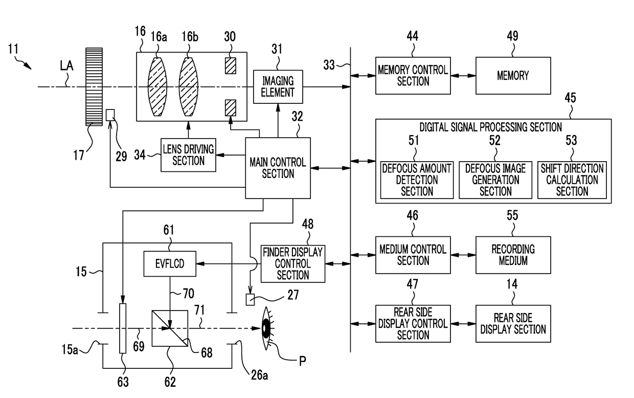
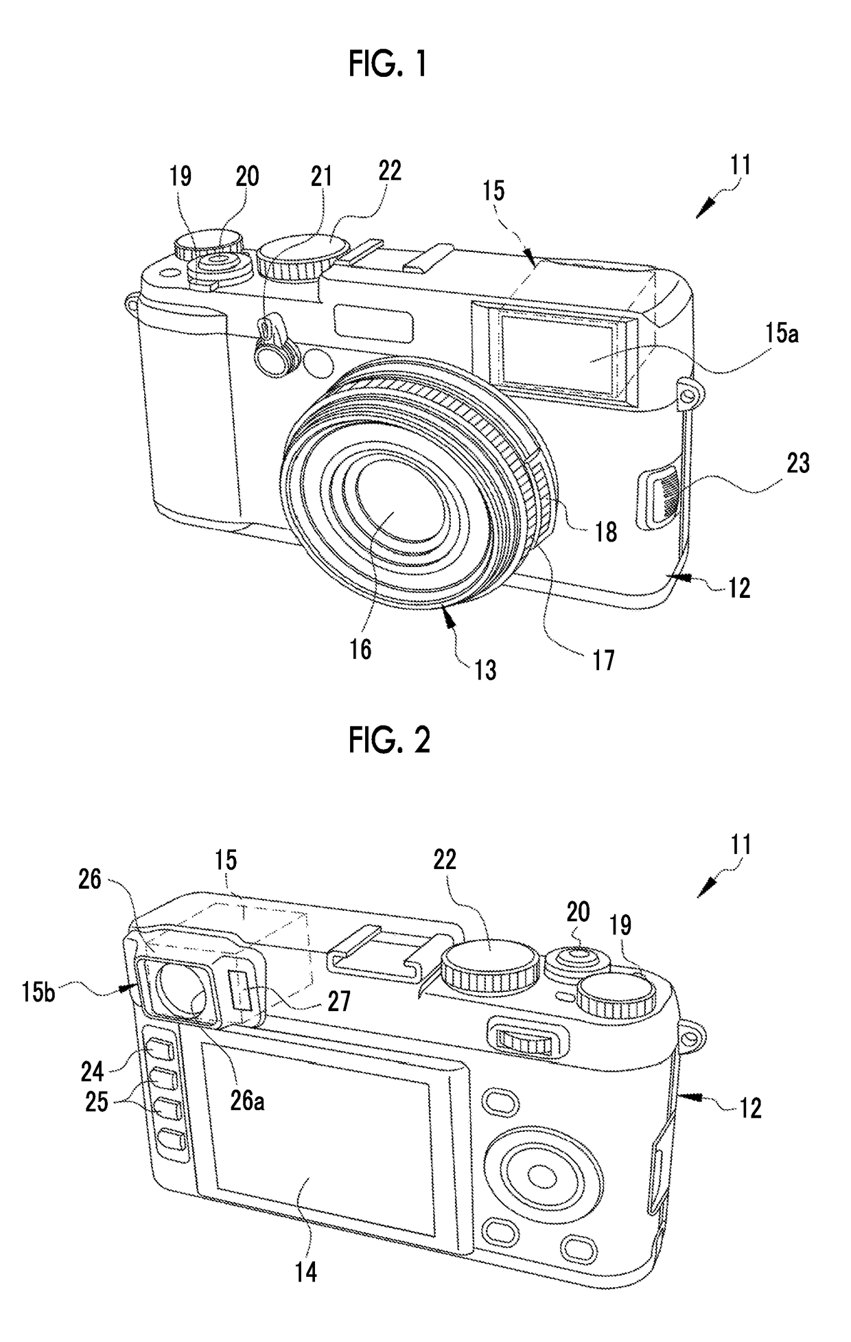
[0044]In FIGS. 1 and 2, a digital camera 11 comprises a camera body 12, a lens barrel 13, a rear side display section 14, and a finder section 15. The lens barrel 13 is provided on the front side of the camera body 12 so as to hold an imaging optical system 16. On the outer periphery of the lens barrel 13, a focus ring 17 (focus adjustment operation section) and a stop ring 18 are rotatably provided. The focus ring 17 and the stop ring 18 are operation members capable of performing focus adjustment and stop adjustment respectively by manually rotating the rings by a photographer.

[0045]The finder section 15 is a hybrid type capable of switching between an optical viewfinder (OVF) mode and an electronic viewfinder (EVF) mode.

[0046]On the upper side of the camera body 12, a power button 19, a release button 20, a shutter dial 22, and the like are provided. On the front side of the camera body 12, a finder switch lever 21, an auto focus / manual focus (AF / MF) changeover switch 23, and the...

second embodiment

[0107]In the first embodiment, the first and second indicators 58 and 59 constituting the defocus image 57 are spaced in the horizontal direction X (first direction), but in the second embodiment, as shown in FIG. 12A, the first and second indicators 58 and 59 are spaced not only in the horizontal direction X but also in the vertical direction Y (second direction) orthogonal to the horizontal direction X. In this case, as the amount of defocus of the imaging optical system 16 is smaller, the first distance D2, which is a distance between the first and second indicators 58 and 59 in the vertical direction Y, is made smaller.

[0108]As shown in FIG. 12B, in a case where the amount of defocus is “0”, that is, in a case where the imaging optical system 16 is brought into focus by the rotation operation of the focus ring 17, both the first distance D1 and the second distance D2 become are “0”, and the first and second indicators 58 and 59 are aligned in a straight line.

third embodiment

[0109]In the third embodiment, as shown in FIG. 13A, a convex portion 58a is provided on a first indicator 58, and a concave portion 59a is provided on a second indicator 59. The convex portion 58a is provided in a portion of the first indicator 58 facing the second indicator 59 in the vertical direction Y. The concave portion 59a is provided in a portion of the second indicator 59 facing the first indicator 58 in the vertical direction Y. The first and second indicators 58 and 59 are spaced in the horizontal direction X and the vertical direction Y, in a manner similar to that of the second embodiment. As shown in FIG. 13B, in a case where the amount of defocus is “0”, that is, in a case where the imaging optical system 16 is brought into focus, the distance between the first and second indicators 58 and 59 becomes “0”, the convex portion 58a and the concave portion 59a are fitted.


PUM


Abstract

The digital camera includes a finder section, an imaging optical system, a focus ring, an eye sensor, an imaging element, a main control section, a digital signal processing section, and a finder display control section. The imaging element outputs first and second imaging signals obtained by receiving the first and second rays formed by performing pupil division on the subject image. The main control section calculates an amount of defocus so as to generate a defocus image, on the basis of first and second imaging signals obtained by receiving first and second rays. The eye sensor detects an eye position P of a photographer who is in contact with the finder section. The finder display control section changes a position, at which the defocus image is displayed, in accordance with the direction of shift of the eye position P.

Description

CROSS-REFERENCE TO RELATED APPLICATIONS[0001]This application is a Continuation of PCT International Application No. PCT / JP2016 / 078712 filed on 28 Sep. 2016, which claims priority under 35 U.S.C § 119(a) to Japanese Patent Application No. 2015-193514 filed on 30 Sep. 2015. The above application is hereby expressly incorporated by reference, in its entirety, into the present application.BACKGROUND OF THE INVENTION1. Field of the Invention[0002]The present invention relates to an imaging device having an electronic view finder or a hybrid view finder and a control method therefor.2. Description of the Related Art[0003]Recently, imaging devices such as a digital camera having an optical viewfinder (hereinafter referred to as an OVF), an electronic viewfinder (hereinafter referred to as an EVF), and a hybrid viewfinder (refer to JP2012-065294A) are known. The hybrid viewfinder has an OVF mode and an EVF mode, and is capable of switching mode between both modes.[0004]The hybrid viewfinde...

Claims


Application Information

Patent Timeline
IPC IPC(8): H04N5/232G03B13/16G02B7/36G02B7/34
CPCH04N5/23293G03B13/16G02B7/36G02B7/34H04N5/23212H04N5/23219G03B13/32G03B17/20G03B13/06G02B27/0093H04N23/53H04N23/672H04N23/61H04N23/611H04N23/633H04N23/634H04N23/635H04N25/704H04N23/63H04N23/67
Inventor TAKAHASHI, KOSUKEMISAWA, ATSUSHI
Owner FUJIFILM CORP
Why Eureka
Try Eureka