Air-conditioning apparatus
- Summary
- Abstract
- Description
- Claims
- Application Information
AI Technical Summary
Benefits of technology
Problems solved by technology
Method used
Image

Examples
embodiment 1
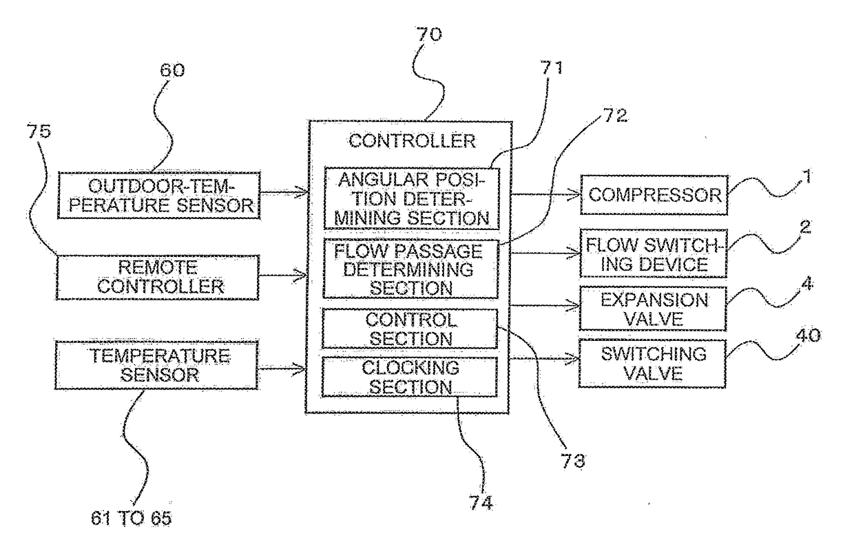
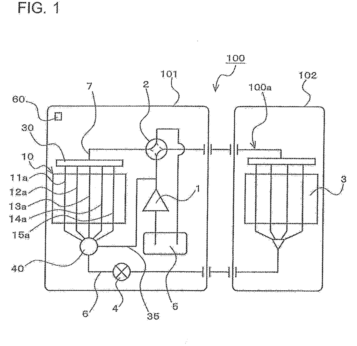
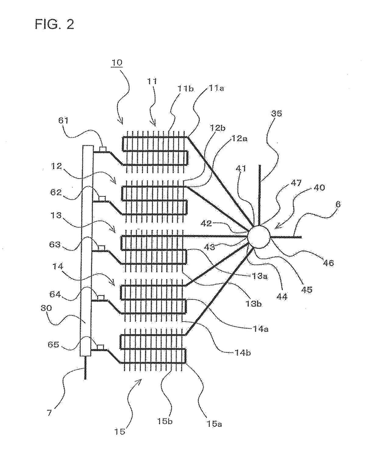
[0027]FIG. 1 is a refrigerant circuit diagram for illustrating an air-conditioning apparatus according to Embodiment 1 of the present invention. FIG. 2 is a refrigerant circuit diagram for illustrating the vicinity of an outdoor heat exchanger of the air-conditioning apparatus. FIG. 3 is a perspective view for illustrating a switching valve of the air-conditioning apparatus. FIG. 4 is a vertical sectional view for illustrating the switching valve of the air-conditioning apparatus. FIG. 5 is a plan view for illustrating the switching valve of the air-conditioning apparatus. Further, FIG. 6 is a hardware configuration diagram and a functional block diagram of the air-conditioning apparatus.
[0028]In FIG. 3 and FIG. 5, for easy understanding of an internal structure of a switching valve 40, a part of the switching valve 40 is illustrated in a transparent manner.
[0029]An air-conditioning apparatus 100 according to Embodiment 1 includes a refrigeration cycle circuit 100a including a compr...
embodiment 2
[0092]The configuration of the switching valve 40 used in the present invention is not limited to the configuration illustrated in Embodiment 1. In Embodiment 2, some other examples of the switching valve 40 are described. In the following, a case in which the outdoor heat exchanger 10 includes three flow passages 11a to 13a connected in parallel, that is, a case in which the switching valve includes three outlets 41 to 43 is described. Further, in Embodiment 2, matters that are not particularly described are similar to those of Embodiment 1, and the same functions and same configurations are denoted by the same reference symbols for description.
[0093]FIG. 11 is a view for illustrating an example of the switching valve of Embodiment 2 of the present invention. The outlined arrows illustrated in FIG. 11 each denote a flow of the low-temperature refrigerant flowing out from the expansion valve 4 during the heating operation. Further, the solid arrows illustrated in FIG. 11 each denote...
embodiment 3
[0105]An on-off valve 36 as described below may be provided in the bypass circuit 35 of the air-conditioning apparatus 100 illustrated in Embodiment 1 or Embodiment 2. Further, in Embodiment 3, matters that are not particularly described are similar to those of Embodiment 1 or Embodiment 2, and the same functions and same configurations are denoted by the same reference symbols for description.
[0106]FIG. 13 is a refrigerant circuit diagram for illustrating the air-conditioning apparatus according to Embodiment 3 of the present invention. Further, FIG. 14 is a hardware configuration diagram and a functional block diagram of the air-conditioning apparatus.
[0107]The air-conditioning apparatus 100 according to Embodiment 3 includes, in the bypass circuit 35, the on-off valve 36 configured to open and close a flow passage of the bypass circuit 35. Further, the controller 70 includes an opening and closing determining section 76 configured to determine opening and closing of the on-off va...
PUM
 Abstract
Description
Claims
Application Information
 - R&D Engineer
- R&D Manager
- IP Professional
- Industry Leading Data Capabilities
- Powerful AI technology
- Patent DNA Extraction
Browse by: Latest US Patents, China's latest patents, Technical Efficacy Thesaurus, Application Domain, Technology Topic.
© 2024 PatSnap. All rights reserved.Legal|Privacy policy|Modern Slavery Act Transparency Statement|Sitemap