

Gas turbine sensor failure detection utilizing a sparse coding methodology
- Summary
- Abstract
- Description
- Claims
- Application Information
AI Technical Summary
Benefits of technology
Problems solved by technology
Method used
Image

Examples
Embodiment Construction
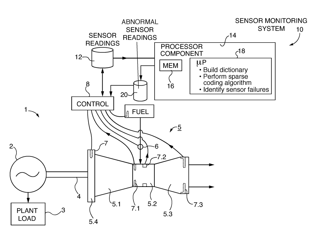
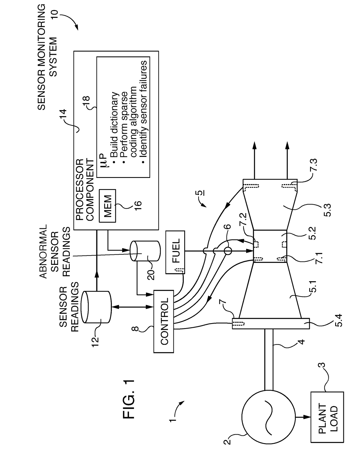
[0022]FIG. 1 is a simplified depiction of a typical gas turbine power plant 1 with a generator 2 supplying a plant electric load 3. Generator 2 is driven by a shaft 4 powered by a gas turbine engine 5. Gas turbine engine 5 is itself comprised of a large number of separate components, including a compressor 5.1, a combustion section 5.2, a turbine 5.3, and, perhaps, a set of adjustable inlet vanes 5.4.
[0023]Fuel is supplied to combustion section 5.2 via a valve 6. In order to maintain acceptable operation of gas turbine power plant 1, a number of sensors 7 are used to monitor the operation of the various components, passing the measured sensor readings to a separate control module 8. Control module 8 may be co-located with gas turbine power plant 1, or may be off-site from the turbine itself. In the diagram of FIG. 1, sensors 7 include a combustor inlet air sensor 7.1, a combustion temperature sensor 7.2, and a blade path temperature sensor 7.3. It is to be understood that there are ...
PUM
 Abstract
Description
Claims
Application Information