Measuring Instrument

a technology of measuring instruments and instruments, applied in the field of measuring instruments, can solve the problems of lengthening the total measurement time, and achieve the effect of improving the efficiency of measuring work and easy sighting of objects

Active Publication Date: 2018-08-16
KK TOPCON
View PDF9 Cites 10 Cited by
  • Summary
  • Abstract
  • Description
  • Claims
  • Application Information

AI Technical Summary

Benefits of technology

[0003]It is an object of the present invention to provide a surveying instrument which can easily sight an object to be measured.
[0013]According to the present invention, the surveying instrument comprises a distance measuring unit which includes a light emitting element for emitting a distance measuring light, a distance measuring light projecting unit for projecting the distance measuring light, a light receiving unit for receiving a reflected distance measuring light and a photodetector for receiving the reflected distance measuring light and producing a light receiving signal, and which performs a distance measurement of an object to be measured based on the light receiving signal from the photodetector, an optical axis deflecting unit provided on a distance measuring optical axis and for deflecting the distance measuring optical axis, a projecting direction detecting unit for detecting a deflection angle of the distance measuring optical axis and an arithmetic control component for controlling a deflecting action of the optical axis deflecting unit and a distance measuring action of the distance measuring unit, wherein the optical axis deflecting unit comprises a pair of optical prisms capable of rotating with the distance measuring optical axis as a center and motors which individually and independently rotate the optical prisms, and wherein the arithmetic control component is configured to control a deflection by the optical axis deflecting unit by controlling rotating directions, rotating speeds, and a rotation ratio of the pair of optical prisms, to perform a two-dimensional scanning of the distance measuring light, to perform a distance measurement of when the light receiving signal is detected during the two-dimensional scanning, to measure a horizontal angle and a vertical angle of the object to be measured based on a deflection angle detected by the projecting direction detecting unit of when the light receiving signal is detected, and to obtain three-dimensional coordinates of the object to be measured based on a distance value from the distance measuring unit, and the horizontal angle and the vertical angle. As a result, the surveying instrument can easily sight the object to be measured, a sighting work by the operator can be omitted, and an efficiency of a measurement work can be improved.

Problems solved by technology

For this reason, there is a trouble that a total measurement time is lengthened.

Method used


Image

  • Measuring Instrument
  • Measuring Instrument
  • Measuring Instrument

Examples


Embodiment Construction

[0025]A description will be given on embodiments of the present invention by referring to the attached drawings.

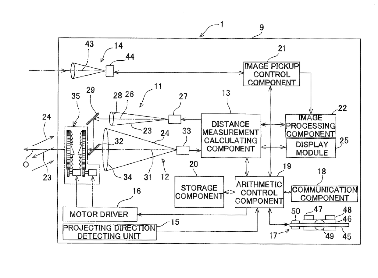
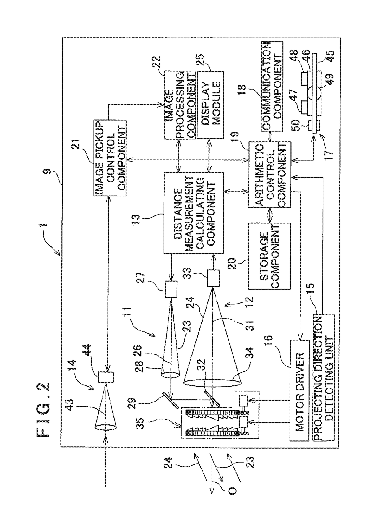
[0026]First, a description will be given on a surveying instrument having a target (or an object to be measured) scanning function, in which the present invention is carried out, by referring to FIG. 1 to FIG. 3. It is to be noted that, in a description as given below, a total station is used as a surveying instrument.

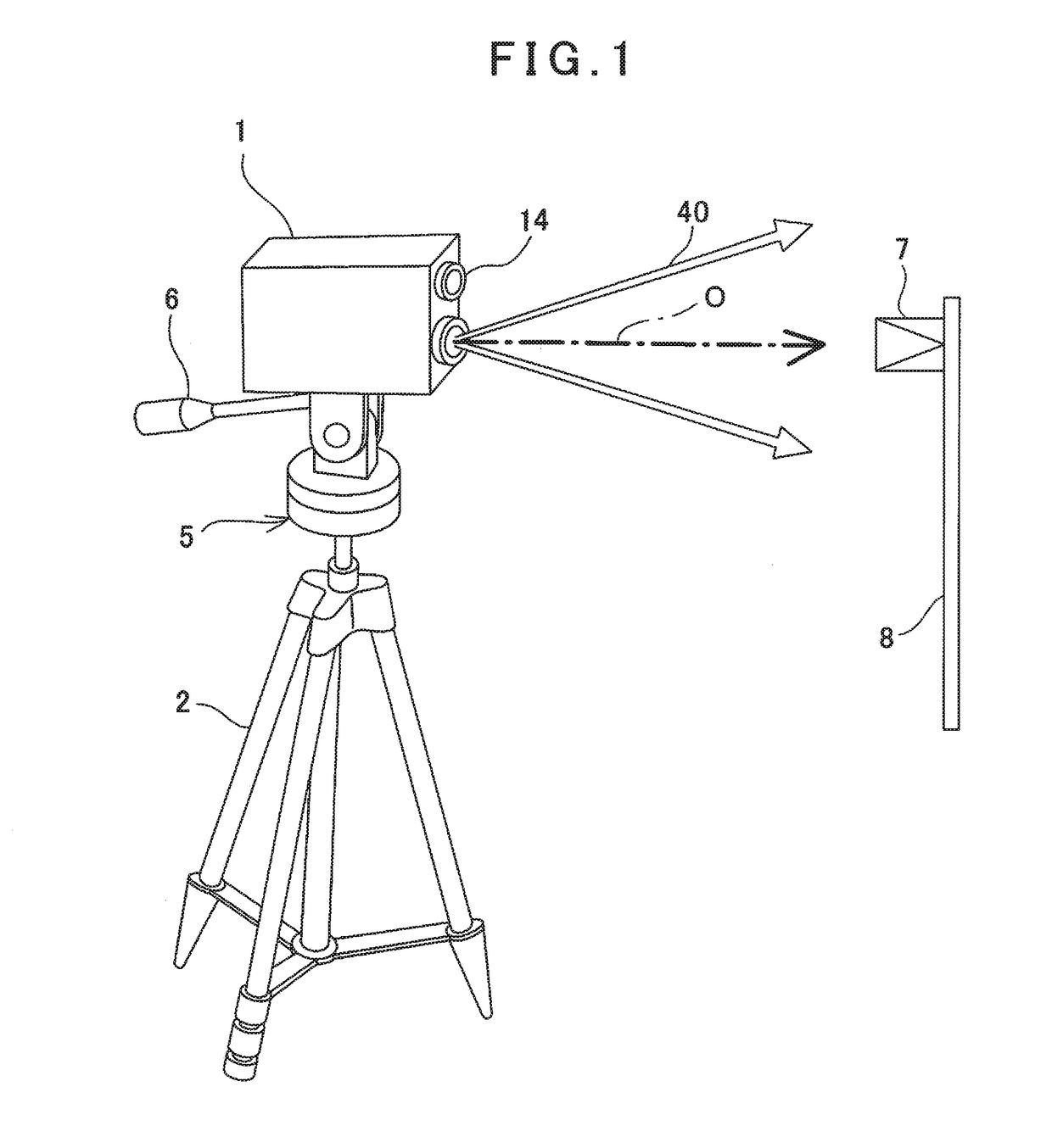
[0027]FIG. 1 shows a state where a total station 1 according to the present embodiment is installed via a tripod 2 as a supporting device. In the drawing, reference sign O denotes an optical axis of the total station 1 and further shows a state where the optical axis is not deflected (a reference optical axis). Further, in FIG. 1, reference numeral 7 denotes a prism as a target or an object to be measured, and the prism 7 is provided in a designated position (for instance, a known position from a lower end) of a pole 8.

[0028]The total station 1 is attached on...


PUM


Abstract

A surveying instrument comprises a distance measuring unit which includes a light emitting element, a distance measuring light projecting unit, a light receiving unit and a photodetector for producing a light receiving signal, and which performs a distance measurement of an object to be measured based on the light receiving signal, an optical axis deflecting unit for deflecting the distance measuring optical axis, a projecting direction detecting unit for detecting a deflection angle of the distance measuring optical axis and an arithmetic control component, wherein the optical axis deflecting unit comprises a pair of optical prisms capable of rotating and motors which individually and independently rotate the optical prisms, and wherein the arithmetic control component is configured to control the optical axis deflecting unit, to perform a two-dimensional scanning of the distance measuring light, to perform a distance measurement of when the light receiving signal is detected, to measure a horizontal angle and a vertical angle of the object to be measured, and to obtain three-dimensional coordinates of the object to be measured based on a distance value, and the horizontal angle and the vertical angle.

Description

BACKGROUND OF THE INVENTION[0001]The present invention relates to a surveying instrument having a target (or an object to be measured) scanning function.[0002]An already existing total station (TS) performs a measurement after a pole with a reflecting component is installed in a measuring position as an object to be measured and an operator manually sights a reflection mirror and the like. Since the total station performs a one-point sighting, in a case where there are two or more measuring positions, the operator changes a sighting position per each measurement and repeats a measurement. In particular, even in a case where a measurement range is narrow, if a measuring position is changed and a position of the reflecting component is even slightly moved, the operator must perform a sighting again. For this reason, there is a trouble that a total measurement time is lengthened.SUMMARY OF THE INVENTION[0003]It is an object of the present invention to provide a surveying instrument whi...

Claims


Application Information

Patent Timeline
Patent Type & Authority Applications(United States)
IPC IPC(8): G01S7/48G01S7/481G01S17/42
CPCG01S7/4808G01S7/4817G01S17/42G01S7/51G01C15/002G01S17/10G01S17/66
Inventor OHTOMO, FUMIOKUMAGAI, KAORU
Owner KK TOPCON
Why Eureka
Try Eureka