Machine tool

a technology of machine tools and tools, applied in the field of machine tools, to achieve the effect of reducing machine size and machine siz

Active Publication Date: 2018-08-23
STAR MICRONICS
View PDF0 Cites 2 Cited by
  • Summary
  • Abstract
  • Description
  • Claims
  • Application Information

AI Technical Summary

Benefits of technology

[0009]The first aspect of the present invention provides a machine tool capable of reducing the machine size. The second and third aspects of the invention provides a machine tool capable of further reducing the machine size.

Problems solved by technology

Such problem is not limited to a lathe provided with a ball screw, but to a machine tool provided with a driving unit having a feed mechanism such as a linear motor stator.

Method used


Image

  • Machine tool
  • Machine tool
  • Machine tool

Examples


Embodiment Construction

[0024]An embodiment of the present invention is being described. The embodiment is only an example of the invention. The features included in the embodiment are not necessarily essential to a solution of the invention.

(1) Summary of Technology Included in the Invention

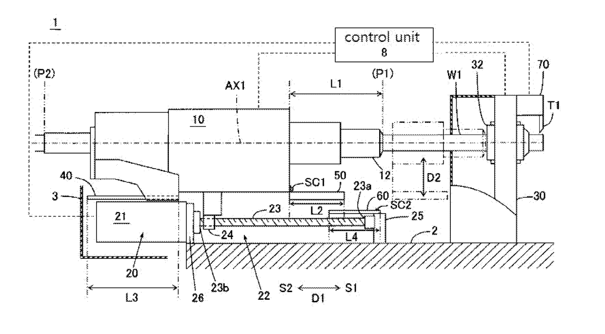
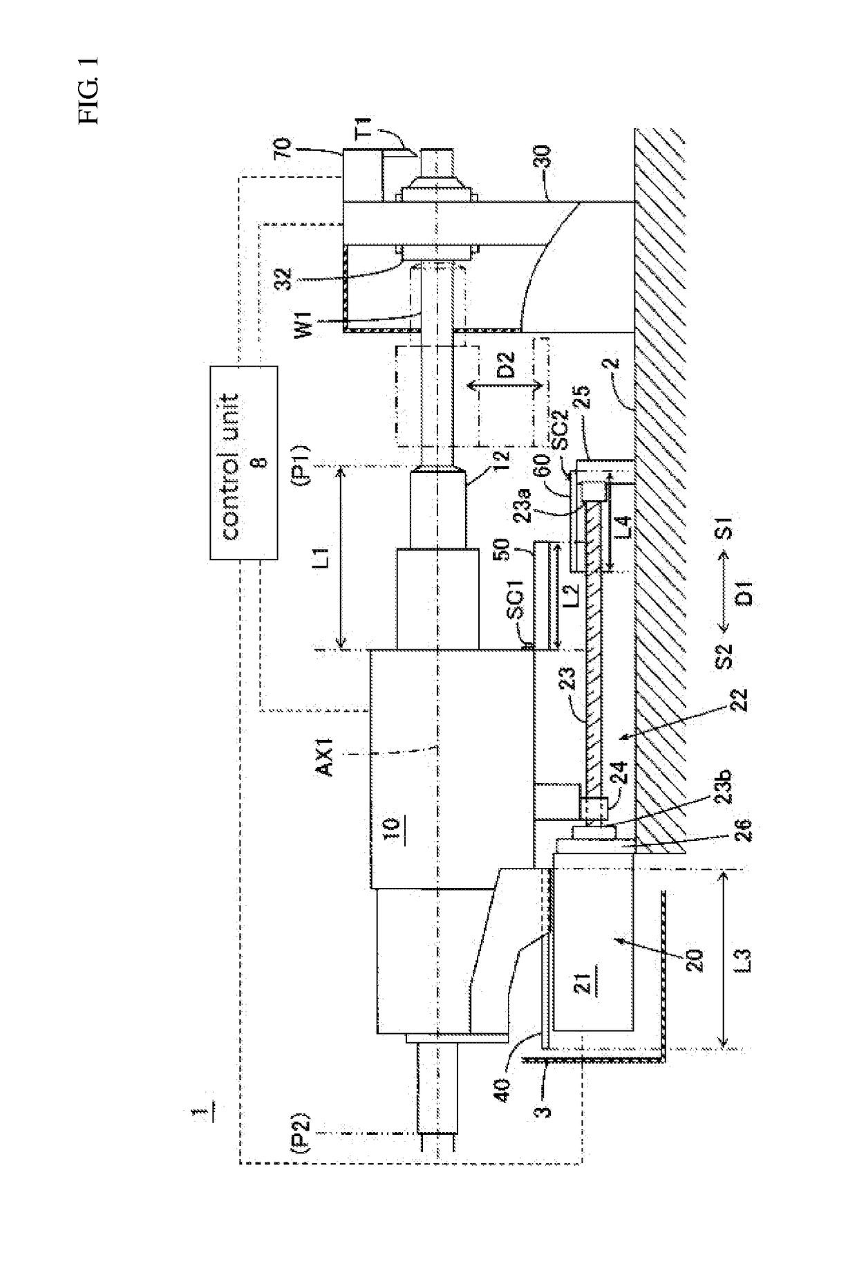
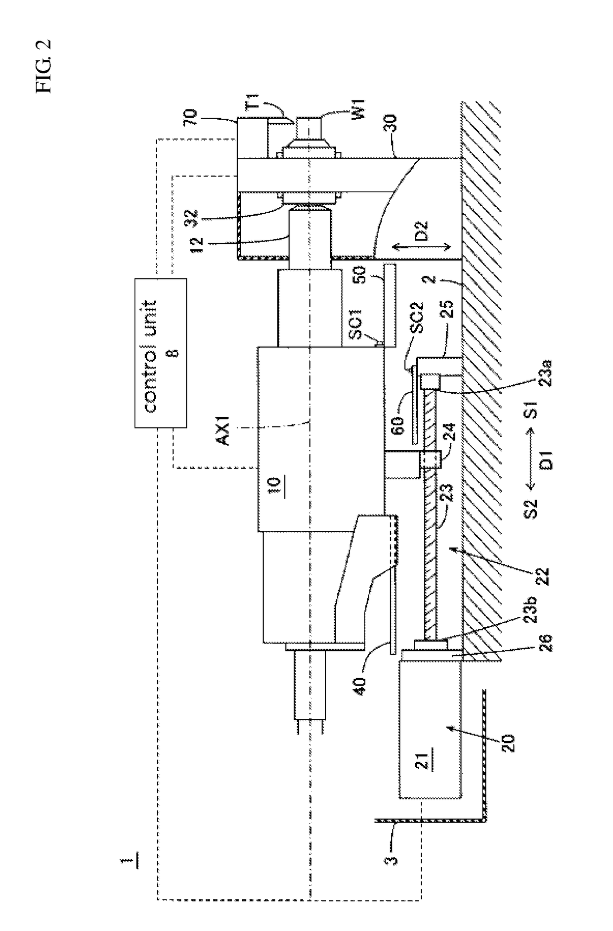
[0025]A summary of technology included in the invention is being described referring to the drawings schematically showing a sliding headstock type lathe 1 as an example of a machine tool. The schematic drawings may have a mismatch to each other due to different magnifications in each direction.

[0026]A machine tool 1 of the invention as illustrated in FIG. 1 to FIG. 8 includes a headstock 10 provided with a main spindle 12 for gripping a workpiece W1, a driving unit 20, a first front cover 50, and a second front cover 60. The driving unit 20 moves the headstock 10 in a main spindle axial direction D1. The driving unit 20 is provided with a feed mechanism 22 extended in the main spindle axial direction D1 and a front en...


PUM

PropertyMeasurementUnit
diameteraaaaaaaaaa
lengthaaaaaaaaaa
dimensionsaaaaaaaaaa

Abstract

The machine tool comprises a headstock provided with a main spindle; a driving unit which moves the headstock in a main spindle axial direction and has a feed mechanism extended in the main spindle axial direction and a front end supporter which rotatably supports a front end of the feed mechanism; a first front cover mounted on the headstock in a first position between the main spindle and the feed mechanism with respect to a diameter direction from a main spindle axis toward the feed mechanism; and a second front cover mounted on the front end supporter in a second position between the main spindle and the feed mechanism. Part of the feed mechanism is covered by both of the first front cover and the second front cover when at least part of the first front cover is on the rear side of the second front cover.

Description

CROSS-REFERENCE TO RELATED APPLICATION[0001]The present application is a continuation of PCT Application No. PCT / JP2016 / 075333, filed on Aug. 30, 2016, which claims priority of Japanese Patent Application No. 2016-016819 filed on Feb. 1, 2016. The contents of this application are incorporated herein by reference in their entirety.BACKGROUND(a) Field[0002]The present invention relates to a machine tool provided with a headstock movable in the axial direction of a main spindle.(b) Description of the Related Art[0003]In a conventional sliding headstock type lathe, a workpiece is slidably supported by a guide bush provided on the front side of a main spindle. A headstock comprising the main spindle is movalble in the axial direction of the main spindle by a driving unit including a ball screw (feed mechanism) extended in the axial direction, a nut mounted on the headstock to be engaged with the ball screw, and a servo motor for rotatably driving the ball screw. The headstock is provided...

Claims


Application Information

Patent Timeline
Patent Type & Authority Applications(United States)
IPC IPC(8): B23Q11/08B23B7/06B23B13/12
CPCB23Q11/0883B23B7/06B23B13/126B23B25/04B23B13/12B23Q5/40B23Q11/0825
Inventor ITO, SHIN
Owner STAR MICRONICS
Why Eureka
Try Eureka