System for secure storage of and controlled access to articles and apparatus therefor

a technology for secure storage and controlled access, applied in coin/paper handlers, coin-freed apparatuses, instruments, etc., can solve problems such as unauthorised access to restricted compartments, system failure, and machine numbers, and achieve the effects of reducing machine size, reducing manufacturing costs, and reducing the number of locking mechanisms

Active Publication Date: 2019-04-23
SMART TOOLS UK LTD
View PDF11 Cites 1 Cited by
  • Summary
  • Abstract
  • Description
  • Claims
  • Application Information

AI Technical Summary

Benefits of technology

[0013]Optionally, said locking arrangement is housed entirely internally within the cabinet and is thereby shielded from external interference.
[0045]Advantageously, the reduced number of locking mechanisms significantly reduces manufacturing cost, reduces machine size, and improves the reliability of dispensing systems. The invention overcomes problems of defeating the locking means by too rapid withdrawal of the drawer by pre-selecting the withdrawal distance of a selected drawer prior to releasing that drawer. The invention simplifies restocking of the drawers, and drawer removal from the cabinet, for re-configuration of the drawer array with different sized drawers, by enabling simultaneous release of all drawers via driving of a single locking bar to a common release position through software control.

Problems solved by technology

Such machines have a number of limitations; most notably that stored items usually require repackaging and / or are dropped from a height into a receiving tray, which is inappropriate for high value precision goods or delicate items.
Furthermore, such solenoid sensor mechanisms require the solenoid locking mechanism only to be actuated once the sensor means indicates to the control system that the drawer has been withdrawn from the cabinet to the required distance.
Disadvantageously, such systems can fail because it can be possible to pull a drawer out more quickly than the latching mechanism can lock it, due to the inherent inertia in the solenoid mechanism and electrical delays.
It is therefore possible to defeat the locking mechanism, leading to unauthorised access to restricted compartments.
Such systems thus require many components, which are expensive and bulky and such systems are not always secure.

Method used


Image

  • System for secure storage of and controlled access to articles and apparatus therefor
  • System for secure storage of and controlled access to articles and apparatus therefor
  • System for secure storage of and controlled access to articles and apparatus therefor

Examples


Embodiment Construction

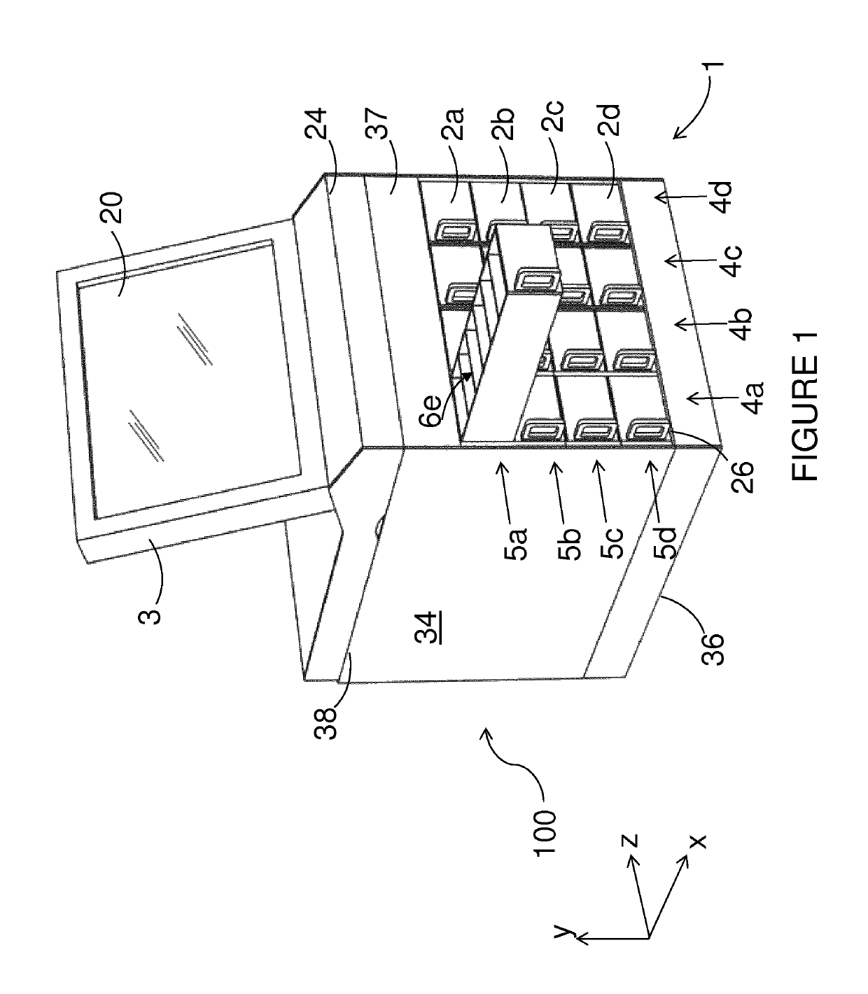
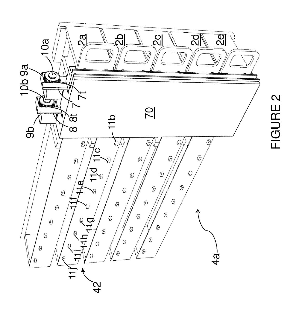
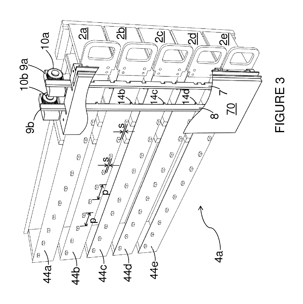
[0062]Detailed descriptions of specific embodiments of the dispensing systems, cabinets, drawers, drawer components and methods of the present invention are disclosed herein. It will be understood that the disclosed embodiments are merely examples of the way in which certain aspects of the invention can be implemented and do not represent an exhaustive list of all of the ways the invention may be embodied. Indeed, it will be understood that the dispensing systems, cabinets, drawers, drawer components and methods described herein may be embodied in various and alternative forms. The Figures are not necessarily to scale and some features may be exaggerated or minimised to show details of particular components. Well-known components, materials or methods are not necessarily described in great detail in order to avoid obscuring the present disclosure. Any specific structural and functional details disclosed herein are not to be interpreted as limiting, but merely as a basis for the clai...


PUM


Abstract

A drawer control means for controlling access to restricted stored items located in compartments in drawers positioned within a cabinet housing a multiplicity of drawers, said drawers being arranged in columns, whereby the drawers in any column can be controlled such that access to a selected drawer and access to a specified compartment within that drawer is effected by only two locking mechanisms per drawer column, and such that the withdrawal distance of a drawer from the cabinet is pre-set prior to the drawer being opened.

Description

[0001]This application is a U.S. national phase application of Intl. App. No. PCT / EP2015 / 054727 filed on Mar. 6, 2015, which claims priority from GB1403986.1 filed on Mar. 6, 2014. The entire contents of PCT / EP2015 / 054727 and GB1403986.1 are incorporated herein by reference.FIELD OF THE INVENTION[0002]The present invention relates to a dispensing system and an apparatus for vending or dispensing articles. More particularly, but not exclusively, the invention relates to a dispensing system for storing high value items that utilises controlled access to such items by locating items in restricted access compartments. The invention finds advantageous application in a wide variety of supply chain applications, for example as a point of sale unit where a consumer directly purchases items, or as an inventory control and storage system for use in a factory or large office housing, for example, tools and components or stationary and office supplies.[0003]Aspects of the invention relate to a ...

Claims


Application Information

Patent Timeline
Patent Type & Authority Patents(United States)
IPC IPC(8): G07F11/62G07F11/00G07F11/18G07F5/26G05B15/02
CPCG07F11/62G05B15/02G07F5/26G07F11/005G07F11/18
Inventor MCFARLAND, JOHN
Owner SMART TOOLS UK LTD
Why Eureka
Try Eureka