Electrical charging arrangement and motor vehicle

Active Publication Date: 2018-08-23
BENTELER AUTOMOBILTECHNIK GMBH
View PDF2 Cites 7 Cited by
  • Summary
  • Abstract
  • Description
  • Claims
  • Application Information

AI Technical Summary

Benefits of technology

[0009]According to an exemplary embodiment, an electrical charging arrangement for a motor vehicle is disclosed, in which the electrical charging arrangement is more powerful in comparison to the prior

Problems solved by technology

It is known from electrical conductors and plug-connections of the electrical charging stations for electric vehicles that the electrical power which can be transmitted at the permissible electrical voltage is limited by the thermal load-bearing ability of the electrical lines and of the plug-in contacts which, on account of the electrical transfer resi

Method used


Image

  • Electrical charging arrangement and motor vehicle
  • Electrical charging arrangement and motor vehicle
  • Electrical charging arrangement and motor vehicle

Examples


Embodiment Construction

[0035]Some embodiments will be now described with reference to the Figures.

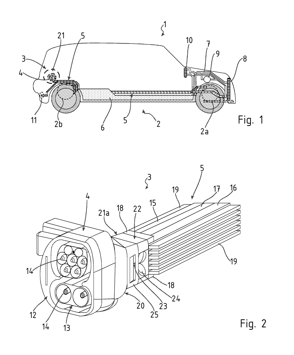
[0036]Referring to FIG. 1, a motor vehicle 1 is shown having an electrical drive system 2 and components of the electrical charging path and also components of the heat management system.

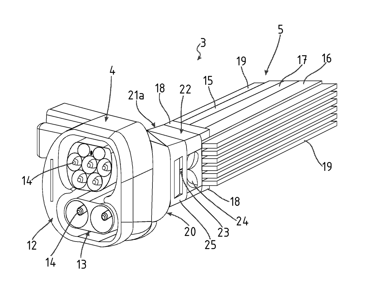
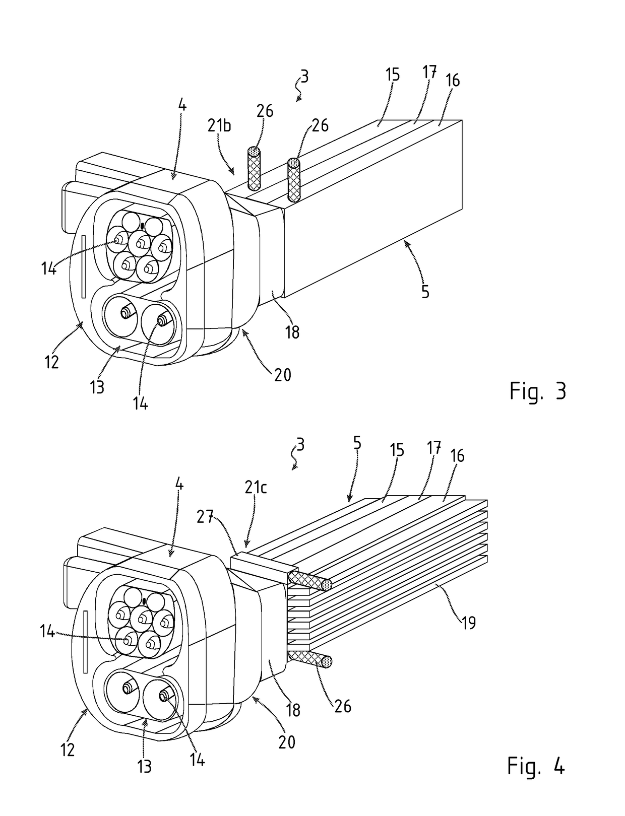
[0037]An electrical charging arrangement 3 comprises a power coupling means 4. The power coupling means 4 is a receiver for conductive power transmission. Electrical energy is fed to the on-board electrical system of the motor vehicle 1 by means of the power coupling means 4. A current conductor 5 extends from the power coupling means 4 as far as an electrical rechargeable battery 6. The current conductor 5 is a high-current conductor.

[0038]Heat carrier channels 7 run at the necessary locations in the motor vehicle 1. The current conductor 5 leads from the power coupling means 4 to the rechargeable battery 6 and from there to the front wheel electric drive 2a and to a rear wheel electric drive 2b. FIG. 1 also illustrates an e...


PUM


Abstract

An electrical charging arrangement in a motor vehicle is disclosed having a power coupling element and at least one current conductor. A cooling element is arranged on the rear side of the power coupling element facing the current conductor so that the power coupling element can be cooled from the rear side.

Description

RELATED APPLICATIONS[0001]The present application claims the priority of German Application Number 10 2017 103 271.1 filed Feb. 17, 2017, the disclosure of which is hereby incorporated by reference herein in its entirety.BACKGROUND1. Field of the Invention[0002]The disclosure is related to an electrical charging arrangement in a motor vehicle having a power coupling element and at least one current conductor, and more specifically, to a heat management apparatus and method in an electrical charging arrangement of an electric vehicle.2. Description of the Related Art[0003]Electric vehicles are becoming increasingly important, and therefore electrification of the drive train in a motor vehicle will further increase in the future. Electric vehicles contain an electric drive and carry an energy store in the form of a rechargeable electric battery or an accumulator battery.[0004]The charging time for the accumulator batteries used at present depends both on the efficiency of the charging...

Claims


Application Information

Patent Timeline
IPC IPC(8): B60L11/18H02G3/03H01B7/42
CPCB60L11/1816H02G3/03H01B7/423H01B7/426B60L53/14B60L53/16H05K7/20136H05K7/20218H05K7/2039B60L3/0023B60L2240/36Y02T10/70Y02T10/7072Y02T90/14H01R2201/26
Inventor GRIENITZ, VOLKERRABE, FRANKBOUGHARDAIN, MOHAMED
Owner BENTELER AUTOMOBILTECHNIK GMBH
Why Eureka
Try Eureka