Suitcase with Retractable Wheels
- Summary
- Abstract
- Description
- Claims
- Application Information
AI Technical Summary
Benefits of technology
Problems solved by technology
Method used
Image

Examples
first embodiment
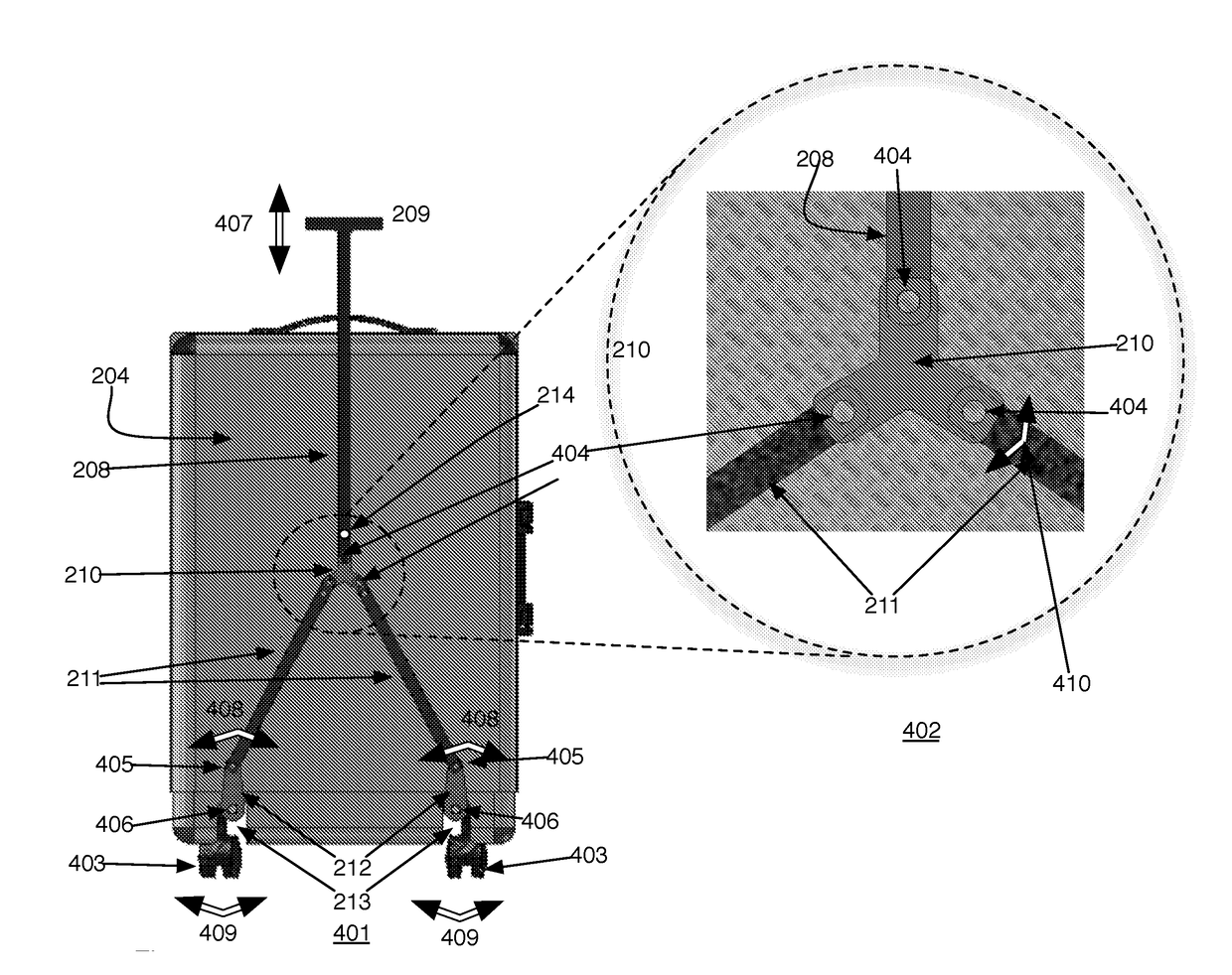
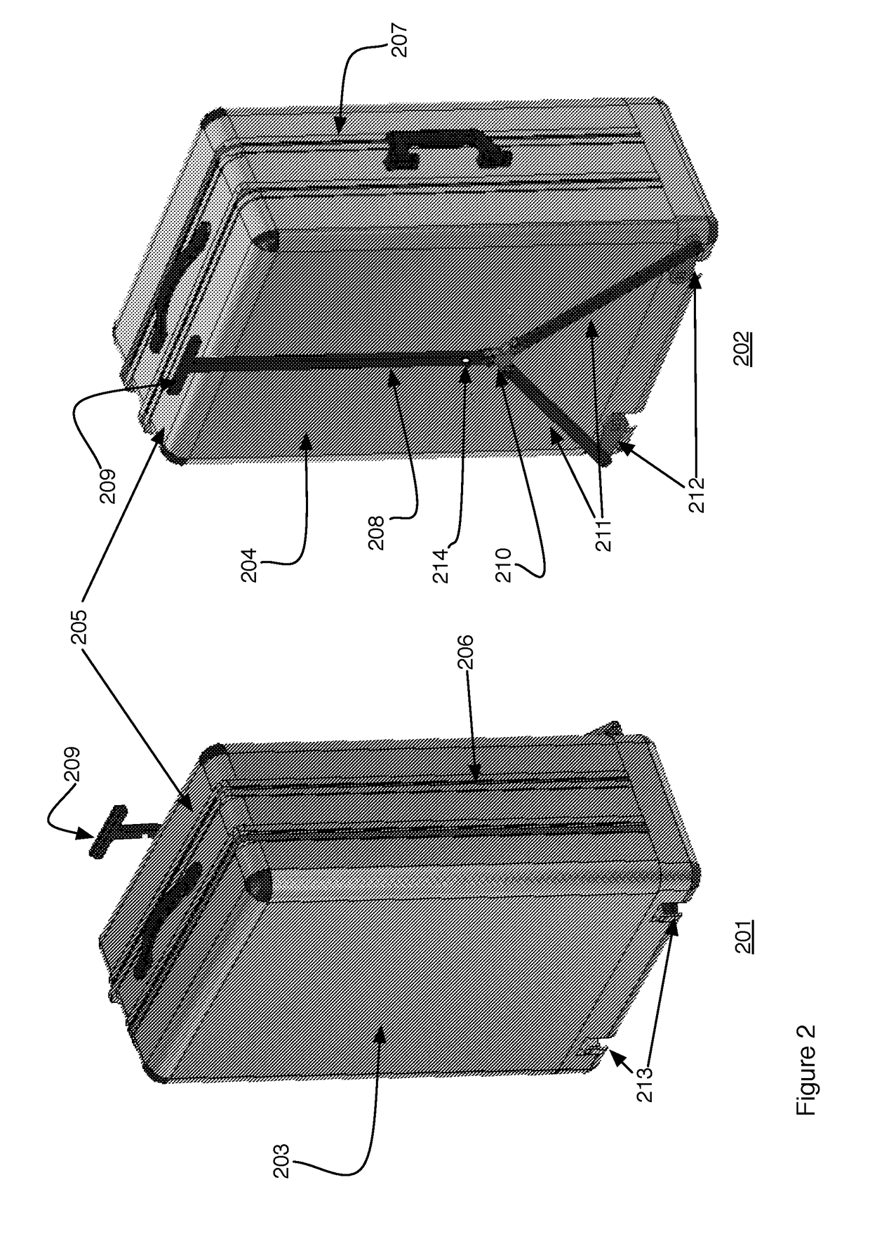
[0031]FIG. 2 a front 201 and a back 202 perspective view of the invented retractable wheel suitcase. The suitcase is comprised a front panel 203, a rear panel 204 and top side 205, a first vertical side 206 and a second vertical side 207. Wheels, retracted and not visible in these views, are attached in cavities 212 on the bottom side, also not visible in these views. A handle 209 is attached to a column 208 held to the backside 204 using a pin 214 in a slot (not visible) in the back side. The pin and slot connection allows the handle 209 and column 208 to be moved in the vertical direction without removing the column from the back of the case. At the end of the column opposite the handle 209 is attached a Y-junction 210. Also attached to the Y-junction 210 are two lower arms 211. The lower arms are further attached to levers 212. The levers are attached to rods supporting the wheels (all seen in later drawings) such that when the handle 209 is raised or lowered the column 208 raise...
second embodiment
[0036]In a second embodiment, shown in FIGS. 7-10 an analogous mechanism is used to retract wheels of a suitcase where, rather than the wheels folding and unfolding in a direction that is perpendicular to the shaft supporting the wheels, the wheels extend and retract vertically.
[0037]Referring to FIG. 7, the case is shown as a front view 701 and a back view 702. The case is comprised of a front 703, a back 704 a top 705, a bottom 706 and two sides 707, 708. Attached to the back of the case is a shaft 709 that includes a handle grip 710 at its top. The bottom end of the shaft is attached to a Y-connector 711. The shaft may be moved up and down in a vertical direction 715. Also attached to the Y-connector 711 are two diagonal arms 712 that are in turn attached to two vertical lower arms 713. Movement of the handle 710 and shaft 709 in the up and down direction also causes the two vertical lower arms to move in an up and down direction 716. The lower end of the vertical arms 713 are at...
third embodiment
[0042]In a third embodiment shown in FIGS. 11-14 the linkage includes telescoping tubes. Referring to FIG. 11, a first view 1110 shows the back 1101 of the suitcase to which the handle and wheel deployment and retraction mechanism is attached. Details of the latching mechanism incorporated into the deployment and retraction mechanism are shown in the second view 1118. The deployment mechanism is comprised of a pair of parallel concentric tubes 1102 that are themselves contained in a concentric housing 1104. Only the outer tube of the concentric tubes 1102 can be seen in the Figure. The concentric tubes are connected at a top end by a handle 1103 and at the bottom end by a horizontal bar 1106. The suitcase user grasps the handle 1103 and pulls upward to extend the wheels and pushes downward to the position shown in the figure to retract the wheels. The bottom horizontal bar 1106 moves upward when the handle 1103 is pulled upward thereby pulling the pair of diagonal arms 1108 upward w...
PUM
 Abstract
Description
Claims
Application Information