
Patient bed for multiple position emission scans

a technology of positron emission and patient bed, which is applied in the direction of motor/generator/converter stopper, ignition automatic control, dynamo-electric converter control, etc., can solve the problems of excessive vibration amplitude and other changes in elevation that are detrimental, and achieve the effect of minimizing the deflection of the support beam

Inactive Publication Date: 2005-04-26
SIEMENS MEDICAL SOLUTIONS USA INC
View PDF5 Cites 63 Cited by
  • Summary
  • Abstract
  • Description
  • Claims
  • Application Information

AI Technical Summary

Benefits of technology

The present invention is a patient bed designed for use with imaging devices such as scanners. The bed has a horizontal rail base and a movable patient surface that can be positioned using an electronic controller. The bed can be moved using a combined PET-CT scanner. The bed includes a magnetic track and a linear motor for horizontal motion, and a vertical track for controlling vertical movement. The bed is designed to not come into contact with the scanner during movement. The technical effects of the invention include improved accuracy and efficiency in positioning the patient for scanning, and reduced risk of damage to the patient and scanner during movement.

Problems solved by technology

As a result, the amplitude of vibration has been known to be excessive.
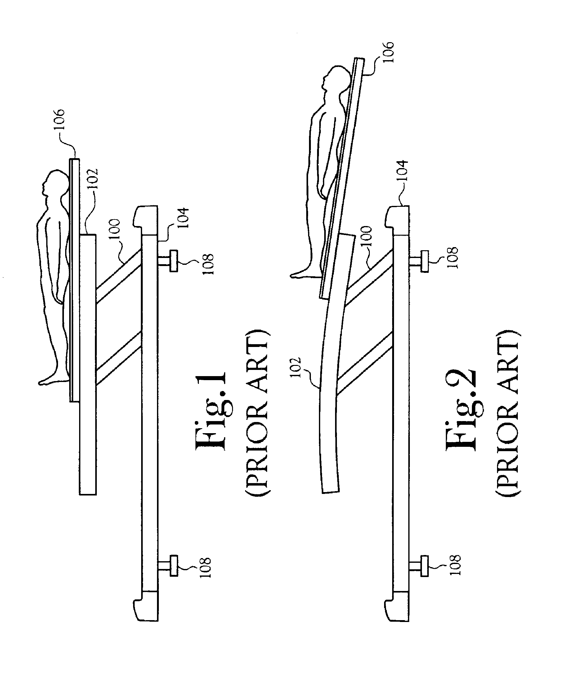
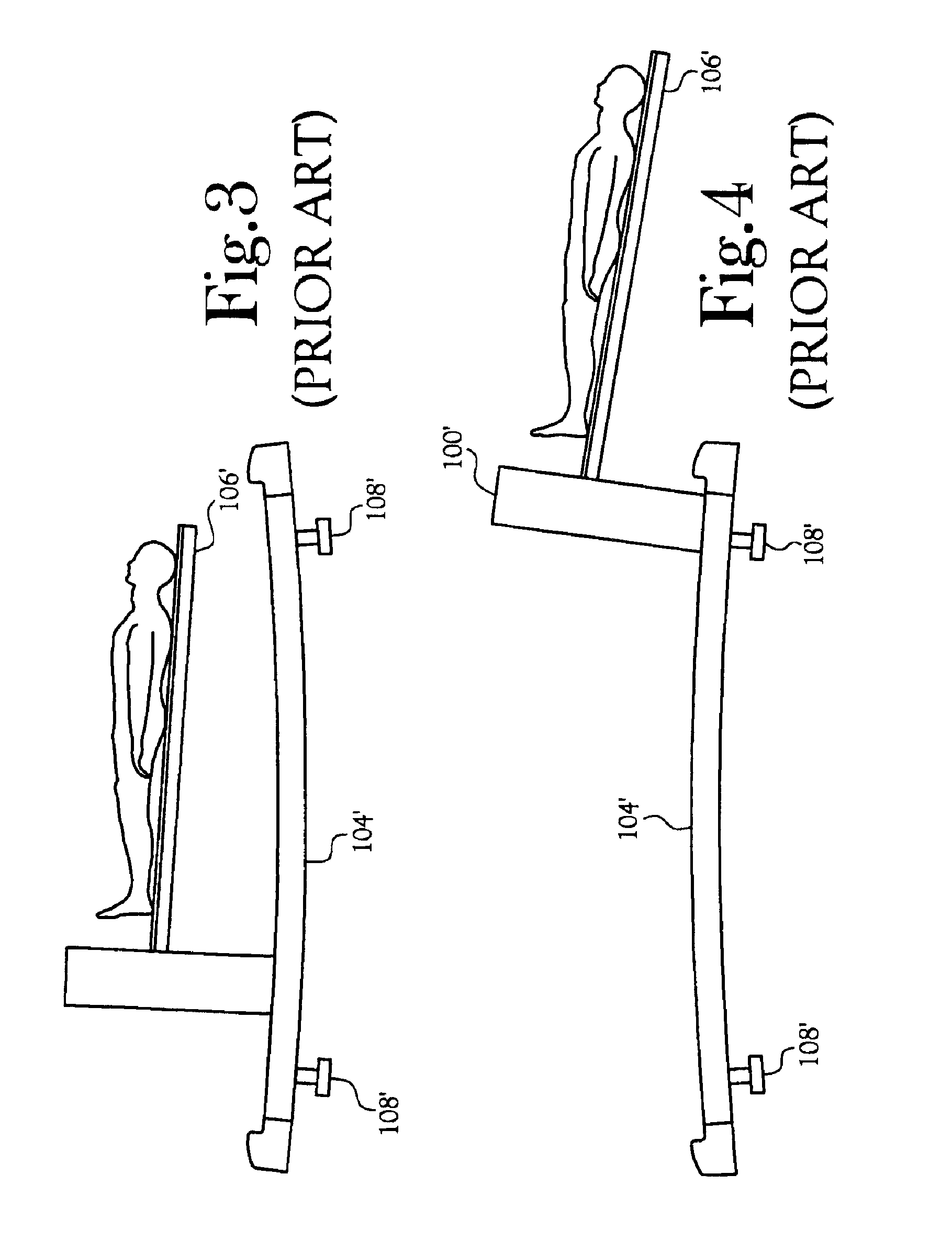
In either of these embodiments, as well as other conventional patient bed supports systems, the deflection resulting from the movement of the patient bed, whether through increased moments as a result of extending the bed, vibration of the bed as a result of movement along the rail bed, or any other change in elevation is detrimental, especially in the case of two imaging devices whose images must be correlated.

Method used


Image

  • Patient bed for multiple position emission scans
  • Patient bed for multiple position emission scans
  • Patient bed for multiple position emission scans

Examples


Embodiment Construction

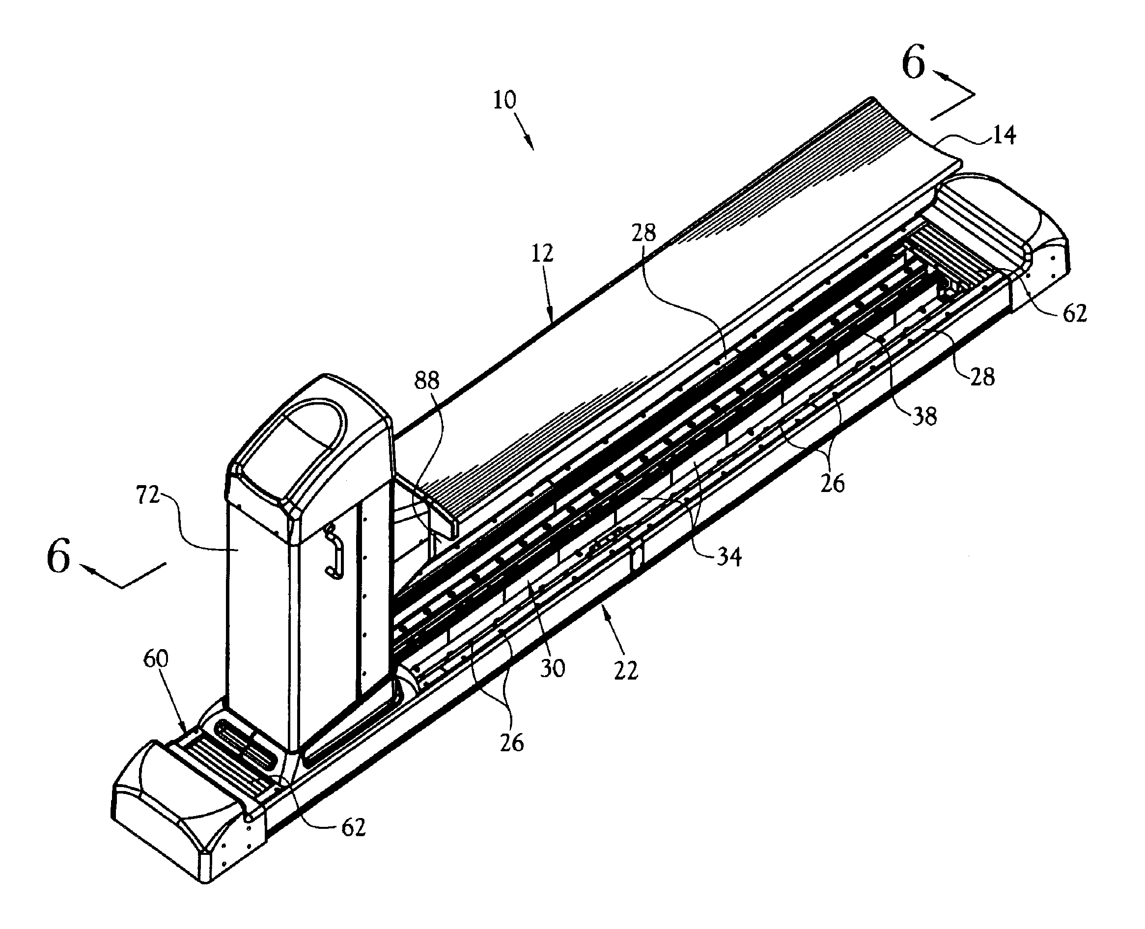
[0031]A patient bed for multiple position emission scans incorporating various features of the present invention is illustrated generally at 10 in the figures. The patient bed 10 is provided for use with at least one imaging device 18, or scanner, in which a plurality of scans are performed, each of the scans being correlated to the other scans. The present invention is useful in a continuous motion scanner used to compile whole-body scans, as well as dual scanners such as a combined Positron Emission Tomography-Computed Tomography (PET-CT) scanner. Although the present invention is described herein with use in conjunction with a combined PET-CT scanner, it will be understood that the patient bed 10 of the present invention is useful in other emission scanners as well.

[0032]The patient bed 10 is controlled to position the patient for the taking of CT and PET fused images. The patient bed 10 is designed to maintain constant vertical positioning of the patient through two scanner fiel...


PUM


Abstract

A patient bed for use with at least one imaging device in which a plurality of scans to be correlated are performed, as well as in a continuous motion scanner used to compile whole-body scans. The patient bed includes a horizontal rail base and a movable patient surface. Electronic controllers are provided for controlling the horizontal and vertical positioning of the patient surface. The horizontal rail base is secured to the support proximate the scanner. A linear motor is used to generate horizontal motion of the patient bed. The linear motor is controlled using a motion controller in communication with a computer associated with the imaging device. A pedestal is provided for mounting a vertical carriage assembly. A vertical track is carried by the pedestal for controlling vertical travel of the patient bed. A motor is provided for controlling vertical motion. A pallet support member is cantilevered from the vertical carriage assembly for carrying a pallet.

Description

CROSS-REFERENCE TO RELATED APPLICATIONS[0001]This application claims the benefit of U.S. Provisional Application No. 60 / 294,713, filed May 31, 2001.STATEMENT REGARDING FEDERALLY SPONSORED RESEARCH OR DEVELOPMENT[0002]Not ApplicableBACKGROUND OF THE INVENTION[0003]1. Field of Invention[0004]This invention relates to the field of Positron Emission Tomography (PET), Computed Tomography (CT) and other related imaging devices. More specifically, the present invention is related to a patient bed for use in one or more such scanning devices which require the bed to be moved between successive scans, and in which the scans are to be used cooperatively to produce an image of the patient.[0005]2. Description of the Related Art[0006]In the field of medical imaging, it is well known that patients are positioned on a bed which is mechanically moved into position within a field of view of a plurality of detectors. Depending upon the type of scanner, two opposing banks of detectors or a continuous...

Claims


Application Information

Patent Timeline
Patent Type & Authority Patents(United States)
IPC IPC(8): A61B6/04
CPCA61B6/0457A61B6/0487
Inventor HENLEY, ALAN W.REYNOLDS, CARLYLE L.
Owner SIEMENS MEDICAL SOLUTIONS USA INC
Learn More