Pipetting apparatus with integrated liquid level and/or gas bubble detection

Active Publication Date: 2006-06-15
TECAN TRADING AG
View PDF10 Cites 62 Cited by
  • Summary
  • Abstract
  • Description
  • Claims
  • Application Information

AI Technical Summary

Benefits of technology

[0031] A pipetting apparatus according to the present invention has (unlike e.g., capacitive or cond

Problems solved by technology

One of the drawbacks of this approach lays in the compressibility of gases, which badly influences or even compromises sensitive and precise detection of pressure changes.
Drawbacks of this approach include a possible covering of the pressure sensor with components of the system liquid.
In addition, moving the liquid-filled tubing (e.g., when the robot moves the pipette tip

Method used


Image

  • Pipetting apparatus with integrated liquid level and/or gas bubble detection
  • Pipetting apparatus with integrated liquid level and/or gas bubble detection
  • Pipetting apparatus with integrated liquid level and/or gas bubble detection

Examples


first embodiment

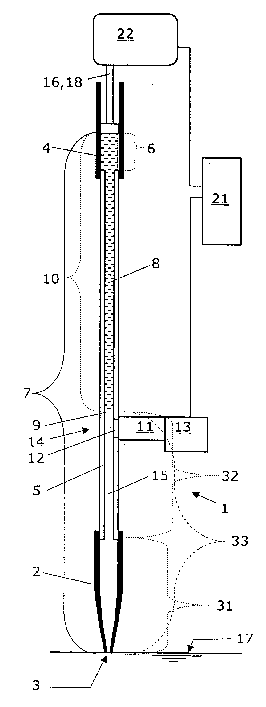
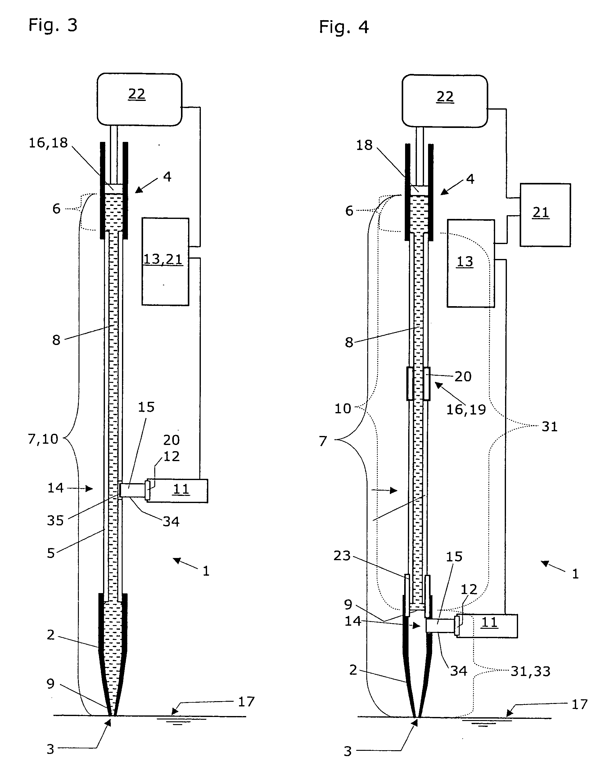
[0076] The advantage of this first embodiment lays in its simple construction, which enables the parallel alignment of a larger number (e.g., 8 or 12) of such pipetters in a robotized sample processing unit (not shown) for example. If only one pipetter channel is fitted to a robot arm (not shown), it may be sufficient to process the data recorded with the pressure transducer 11 by the first data processing unit 13. Control of the drive 22 of the pump may be carried out manually.

[0077] If, however an automated pipetter or even a multitude of such automated pipetters are aligned on a robot arm of a laboratory work station (not shown), it is preferred that a second data processing unit 21 is connected to the motor drive 22 of the pump 4 and to the first data processing unit 13 in order to monitor this motor drive 22 according to the pressure variation in the gas filled space 15, as recorded by the pressure transducer 11 and processed by the first data processing unit 13. All pipetters ...

second embodiment

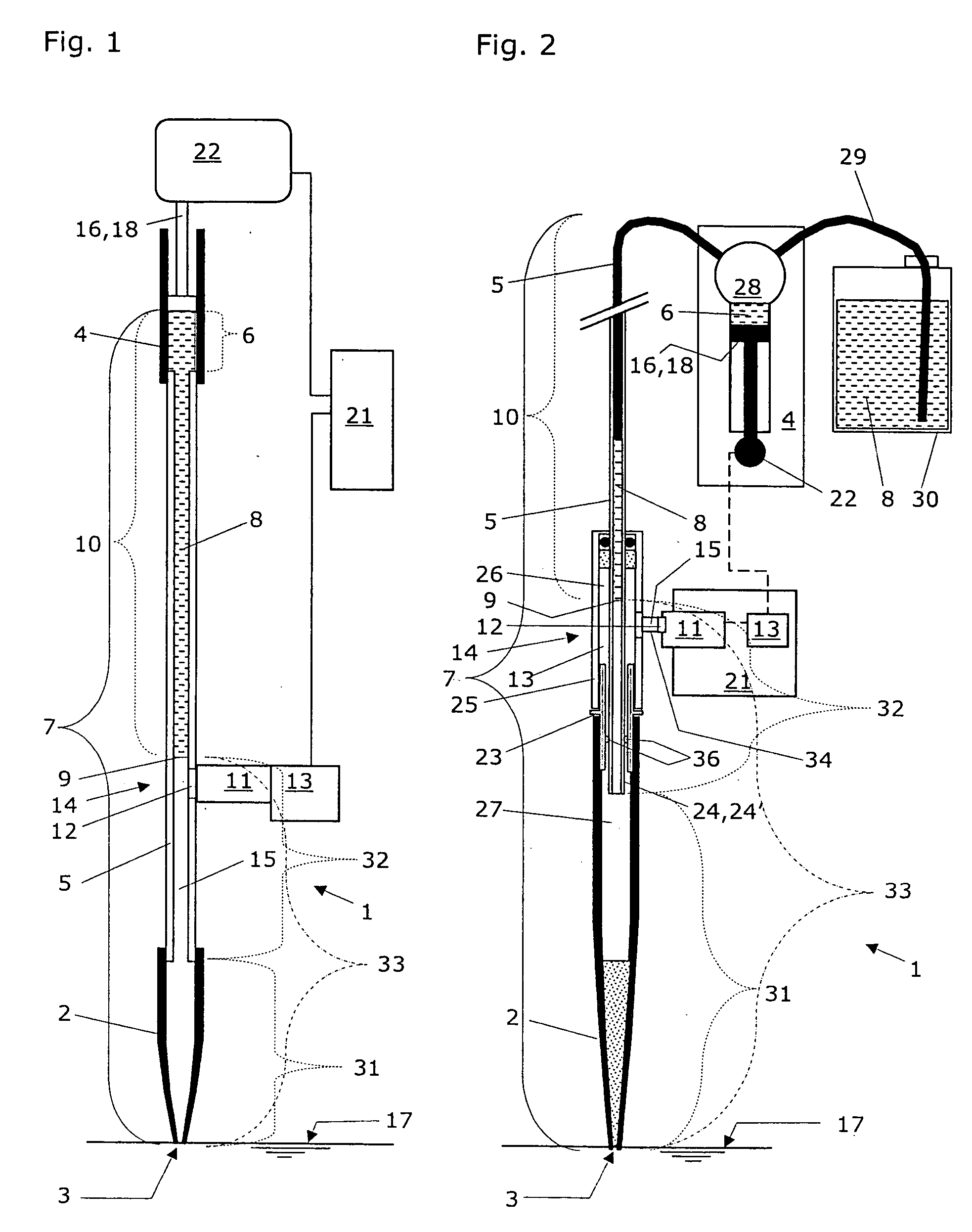
[0079] The advantage of this second embodiment lays in its complete separation of system liquid 8 and sample liquid inside the pipette tip 2. With this preferred construction, mixing of system liquid and sample liquid is avoided. Also here it is preferred that a second data processing unit 21 is connected to the motor drive 22 of the pump 4 and to the first data processing unit 13 in order to monitor this motor drive 22 according to the pressure variation in the gas filled space 15, as recorded by the pressure transducer 11 and processed by the first data processing unit 13. All pipetter channels can be individually controlled with the second data processing unit 21, which is integrated in each individual pipetter. The central computer of a laboratory workstation may achieve the synchronization of all pipetter channels.

[0080] The inner tubing 24 may be accomplished in a first embodiment as a continuous tubing constituted of one single plastic piece of the first tubing 5 that reaches...


PUM


Abstract

A pipetting apparatus (1) comprises a fluidic space (7), to which a pressure transducer (11) with a pressure sensor (12) is attached with a gas filled space (15). The fluidic space (7) is defined by a pipette tip (2), a first tubing (5) that connects the pipette tip (2) to a pump (4), and an active part (6) of the pump (4). The pipetting apparatus (1) according to the present invention is characterized in that the pipetting apparatus (1) further comprises an impulse generating means (16,18,19) that is in operative contact with a column (10) of system liquid (8) inside the fluidic space (7). The impulse generating means (16,18,19) is designed to induce a vertical movement in this system liquid column (10), which results in a pressure variation in the gas filled space (15) that is pneumatically connected with the fluidic space (7). This pressure variation—as recorded with the pressure transducer (11) and as processed by a first data processing unit (13) during utilization of this pipetting apparatus—is taken as an indicator for the detection of penetration or of quitting of a surface (17) of a liquid, with an orifice (3) of the pipette tip (2), of which liquid an amount is to be aspirated and dispensed. This pressure variation is also taken as an indicator for the detection of the presence or the absence of gas bubbles in the system liquid (8) contained in the fluidic space (7) of this pipetting apparatus.

Description

RELATED FIELD OF TECHNOLOGY [0001] The present invention relates to a pipetting apparatus for the aspiration (or uptake) and dispensation (or delivering) of volumes of liquids, such as liquid samples. A pipetting apparatus of this type comprises a pipette tip with a pipette orifice and a pump. The pipette tip usually is connected to the pump by a first tubing. An active part of the pump, the first tubing and the pipette tip are defining a fluidic space. This fluidic space is at least partially filled with a system liquid, such that a meniscus is formed in the fluidic space at an end of a substantially continuous system liquid column. The typical pipetting apparatus further comprises a pressure transducer with a pressure sensor and a first data processing unit that is designed to process the data received from the pressure transducer. The pressure transducer is connected to the fluidic space via a connection site. The present invention also relates to a method of detecting the surfac...

Claims


Application Information

Patent Timeline
IPC IPC(8): B01L3/02
CPCG01N35/1009Y10T436/2575Y10T436/119163G01F23/185
Inventor BJORNSON, TORLEIF OVELIEBHARD, ROBERTZUPPIGER, ADIHEERKLOTZ, DIRK
Owner TECAN TRADING AG
Why Eureka
Try Eureka