Control switch apparatus

a control switch and apparatus technology, applied in the direction of mechanical control devices, gearing, instruments, etc., can solve the problems of increasing the number of discs provided in the control switch apparatus, restricting the range of rotational operation, and affecting the operation of the control switch

Inactive Publication Date: 2008-08-21
KK TOKAI RIKA DENKI SEISAKUSHO
View PDF5 Cites 66 Cited by
  • Summary
  • Abstract
  • Description
  • Claims
  • Application Information

AI Technical Summary

Benefits of technology

[0049]According to the present configuration, the operation restriction mechanism for setting enabling or disabling of operation of the operating portion can be handled as a single unit component. Therefore, at the time of manufacture of a control switch having an operation restriction mechanism, the essential requirement is to assemble an existing control switch unit into the unit component. Implementation of the invention becomes easy in this case.
[0050]According to the present invention, there can be provided an operation restriction mechanism for imparting an operation range to an operating portion through a smaller number of processes for machining components.
[0051]According to the present invention, a click feeling developing in one control switch can be switched by means of a small number of components.

Problems solved by technology

When the engagement portion contacts the engaged portion during rotation of the dial knob, further rotation of the dial knob is restricted, thereby restricting the range of rotational operation.
Hence, the number of discs provided in the control switch apparatus becomes greater, which in turn leads to a fear of an increase in the size of the control switch apparatus.
Moreover, when the number of components of discs increases, component costs are correspondingly incurred in the discs, and there is a fear of this leading to an increase in the component costs.

Method used


Image

  • Control switch apparatus
  • Control switch apparatus
  • Control switch apparatus

Examples


first embodiment

[0078]A first embodiment of a control switch embodying the present invention will be described hereunder by reference to FIGS. 1 through 9.

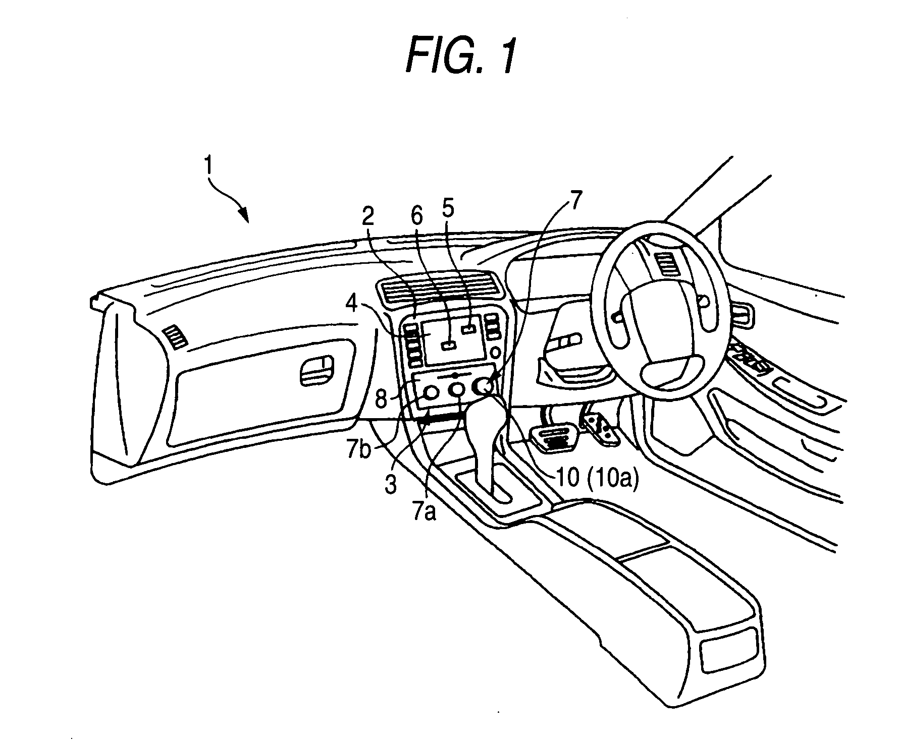
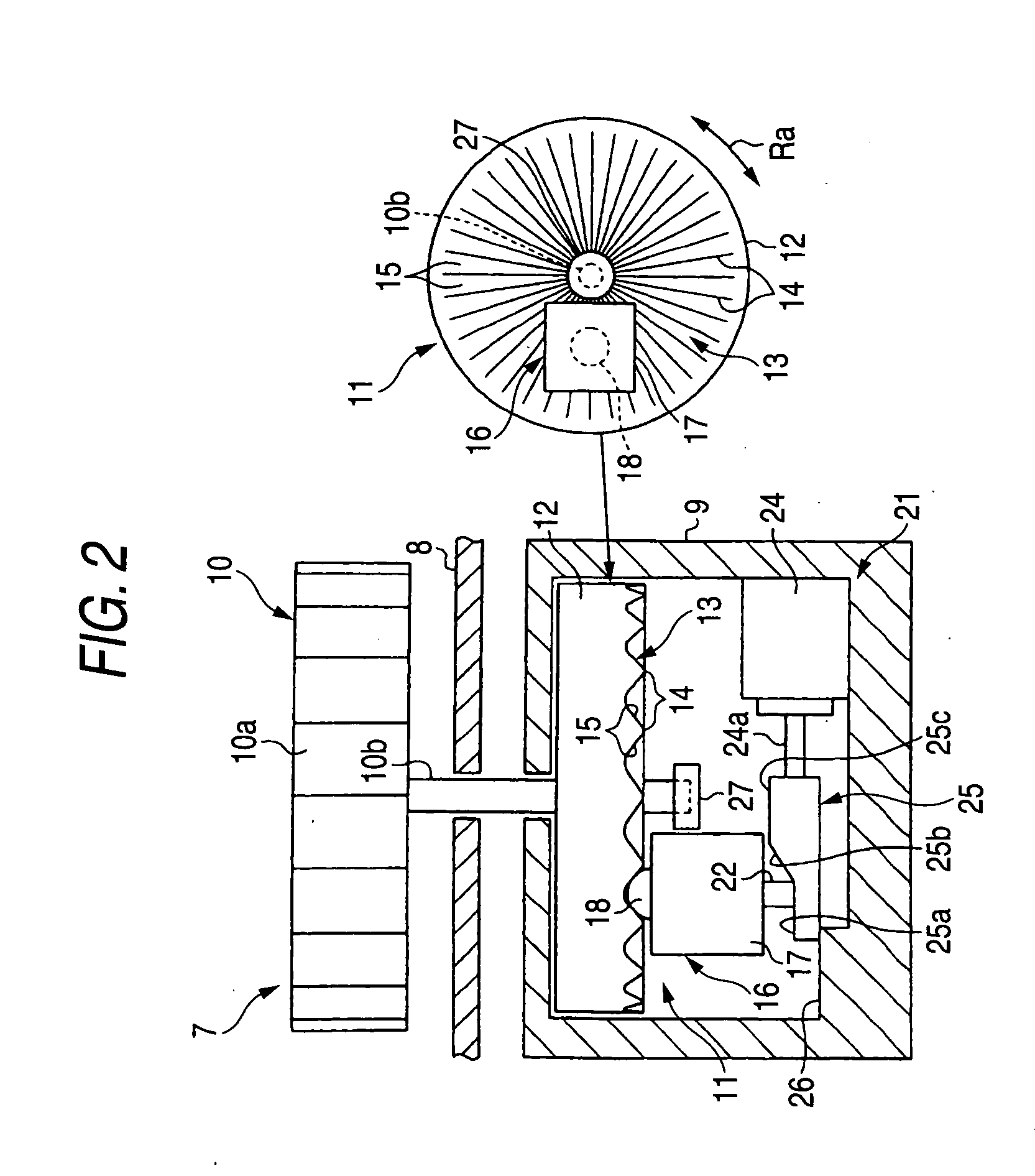
[0079]As shown in FIG. 1, a center cluster 2 of a vehicle 1 is equipped with a control switch apparatus 3 as an operation system for various types of vehicle-mounted equipment, such as an air conditioner, an audio system, and a car navigation system. The control switch apparatus 3 of the present embodiment uses a graphical user interface (GUI) with a view toward enhancing visibility or operability achieved during operation for selecting a button. In the control switch apparatus 3 of graphical user interface type, an item button 5, an icon 6, and the like, are graphically displayed on a display 4 mounted in the center cluster 2. While selecting and designating the item button 5, the icon 6, or the like, on the display 4 by means of a control switch 7 provided in the center cluster 2, input operation is performed by use of a determination switch 7a...

second embodiment

[0112]A second embodiment will now be described by reference to FIGS. 10 and 11. Since the second embodiment has the same configuration as that of the first embodiment except a change in the structure of the operation restriction mechanism 21 of the first embodiment. Hence, like elements are assigned like reference numerals, and their detailed explanations are omitted, and explanations are given solely to a difference between these embodiments.

[0113]As shown in FIG. 10, the control switch apparatus 3 is provided with an electromagnetic solenoid 41 as a drive component (a drive source) for the operation restriction mechanism 21. The electromagnetic solenoid 41 is provided with a solenoid case 42 for housing various types of solenoid components, and the solenoid case 42 is fixed to an interior wall surface of the switch case 9. An electromagnet (coil) 43 serving as a source for generating power of the electromagnetic solenoid 41 is provided in the solenoid case 42. A movable shaft 43a...

third embodiment

[0119]A third embodiment will now be described by reference to FIGS. 12 and 13. Since the third embodiment has the same configuration as that of the first embodiment except a change in the structure of the operation restriction mechanism 21 of the first embodiment. Hence, even in the present embodiment explanations are given solely to a difference between these embodiments.

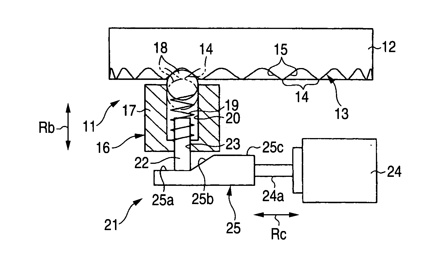
[0120]As shown in FIG. 12, the piece 18 and the stopper 22 of the present embodiment are built as a stopper-equipped detent piece 18a (hereinafter called simply “stopper-equipped piece”) in which the piece 18 and the stopper 22 are integrally assembled together. The stopper-equipped piece 18a of the present embodiment is attached to the plunger case 17 while being able to reciprocally move along the urging direction of the urging member 19. In a case where the stopper-equipped piece 18a is not locked when the dial knob 10 is rotationally operated, the stopper-equipped piece 18a of stopper-integrated type makes mot...


PUM


Abstract

A control switch is equipped with a detent mechanism that generates a click feeling in a dial knob as a result of a detent piece of a plunger member gets over detent crests of a detent crest member. A stopper is provided in the plunger member, and the position of vertical motion of the stopper is switched by means of a rectilinear actuator, thereby switching rotational operation of the dial knob between an enabled state and a disabled state.

Description

BACKGROUND OF THE INVENTION[0001]The present invention relates to a control switch apparatus capable of setting operation of the control switch in an “enabled” or “disabled” state and relates to a detent changeover switch capable of switching a click feeling developing in an operating portion of a control switch.[0002]A vehicle has hitherto been equipped with a variety of control switches that are operated at the time of activation of various vehicle-mounted devices, such as an air conditioner, audio equipment, and a car navigation system. Often used as the control switch of this type is a rotary switch that enables selection and designation of various operating functions, such as switching power of a vehicle-mounted device between an ON position and an OFF position, selection of a functional item, and operation pertaining to an amount of operational control, by means of rotation of a dial knob serving as an element to be operated. An example of such a rotary switch is described in ...

Claims


Application Information

Patent Timeline
Patent Type & Authority Applications(United States)
IPC IPC(8): H01H19/00F16H35/18
CPCB60K37/06B60K2350/102G05G1/10G05G5/03H01H19/11G05G5/065H01H3/50H01H9/24G05G5/04B60K2370/126B60K2370/158
Inventor ISHIGAKI, SEIJIHIROE, TERUKAZU
Owner KK TOKAI RIKA DENKI SEISAKUSHO
Why Eureka
Try Eureka