Electricity producing flexible and slim nozzle for being releasably connected to a suction source of a vacuum cleaner

a technology of electric power generation and suction source, which is applied in the direction of suction nozzles, electric equipment installation, cleaning equipment, etc., can solve the problems of reducing the efficiency of electricity generation, obstructing the rotation of the fan, and total stop of electricity generation,

Active Publication Date: 2018-08-30
APIROS AB
View PDF4 Cites 1 Cited by
  • Summary
  • Abstract
  • Description
  • Claims
  • Application Information

AI Technical Summary

Benefits of technology

[0007]There is a complex of problems associated with the nozzles described in prior ar

Problems solved by technology

One of the disadvantages with this type of nozzle (brush) is that dust, dirt, hair, string, lacing, twine, cords and yarn which is sucked from the surface to be cleaned enters the suction inlet (5) and then gets tangled in the fan (2) thereby obstructing the fan from rotating.
The obstruction not only lowers the efficiency of electricity generation, but leads eventually to the complete failure of the fan and total stop of electricity generation.
Moreover, once the fan is partially or completely obstructed from rotating, dirt and dust then clog up the space between the fan and the fan housing which leads to further obstruction of the fan as well as the nozzle being clogged by dust and dirt.
Clumps of dust, i.e. dust bunnies, are especially responsible for the failure of the fan as well as the clogging of the nozzle.
They can also house dust mites or other parasites, and can drastically lower the efficiency of the fan.
A further disadvantage of the nozzle (brush) in WO2009/078050 is that it is impossible for the operator to remove obstructions from the fan since as illustrated in FIGS. 3 the underside of the nozzle (brush) is covered with one or more plates which must be removed (or unscrewed) with at least one tool.
Such tools might be not be available to the operator, or that the operator does not have knowledge in opening up and repairing nozzles.
Hence, the operator must leave the nozzle to an authorized repair person which generates unnecessary costs and time loss for the operator.
A further disadvantage with the nozzle in WO2009/078050 is that the freedom of rotation of the nozzle relative to the pipe union (4) is restricted. FIGS.

Method used


Image

  • Electricity producing flexible and slim nozzle for being releasably connected to a suction source of a vacuum cleaner
  • Electricity producing flexible and slim nozzle for being releasably connected to a suction source of a vacuum cleaner
  • Electricity producing flexible and slim nozzle for being releasably connected to a suction source of a vacuum cleaner

Examples


Embodiment Construction

[0058]There is a complex of problems associated with the nozzles described in prior art documents. Hence, the aim of the present invention is to eliminate said complex of problems.

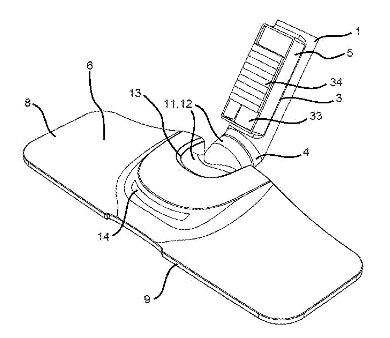
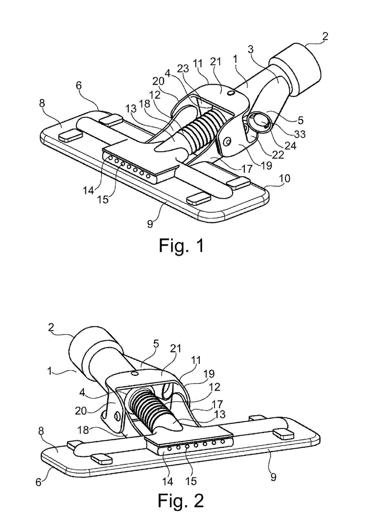
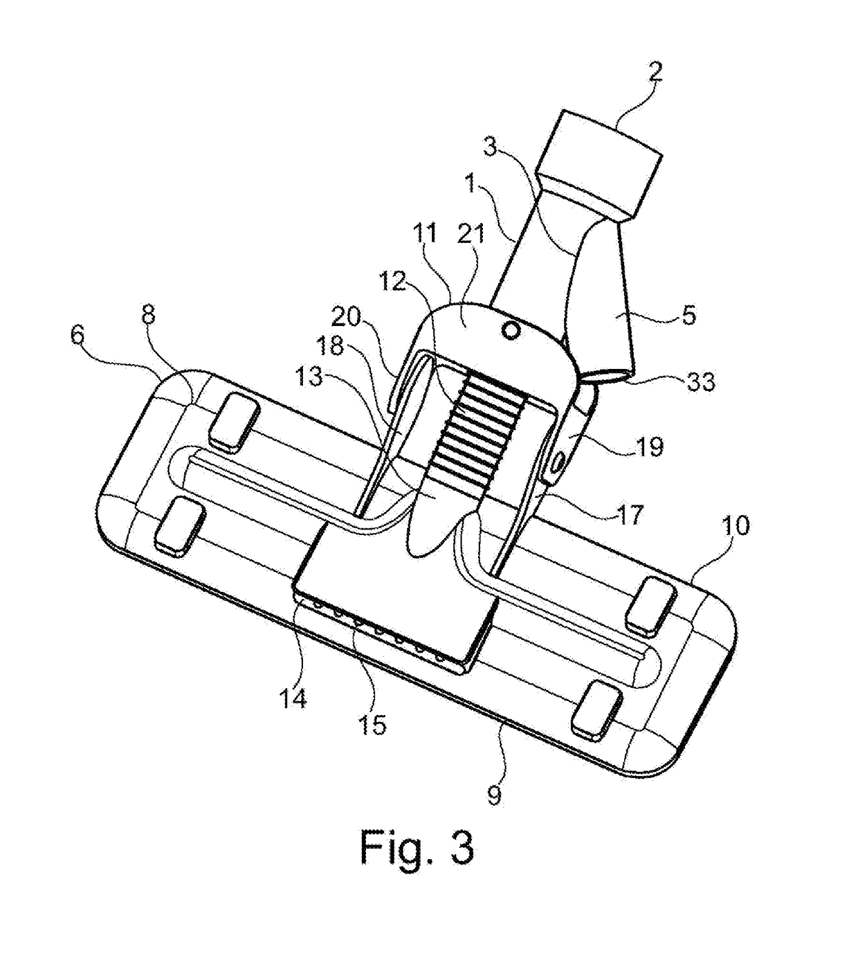
[0059]Referring to FIGS. 1-4, a nozzle according to a specific example of the present invention comprises a nozzle tube 1, a slim nozzle head 6, a flexible joint 11, a flexible conduit 12, a light source 14 and a power generation device 16.

[0060]The nozzle tube 1 has an upper opening 2, a side opening 3 and a lower opening 4. The upper opening 2 is configured to be connected to a suction source of a vacuum cleaner. A suction source may be an extension tube (from now on referred to as a tube), pipe union, hose or any other conduit for connecting a nozzle with the vacuum generation unit of a vacuum cleaner. The upper opening 2 of the nozzle tube 1 may be configured as a connection having 2-5 different diameters for being fitted with a variety of suction source tubes having different diameters.

[0061]The heigh...


PUM


Abstract

The present invention relates to a nozzle suitable for being releasably connected to a suction source of a vacuum cleaner. The nozzle comprises a nozzle tube, a slim nozzle head, a flexible joint configured to provide a freedom of movement, a flexible conduit, a light source, and a power generation device.

Description

TECHNICAL FIELD[0001]The present invention relates to a nozzle suitable for being releasably connected to a suction source of a vacuum cleaner. The nozzle comprises a nozzle tube, a slim nozzle head, a flexible joint configured to provide a freedom of movement, a flexible conduit, a light source, and a power generation device.BACKGROUND OF THE INVENTION[0002]WO2009 / 078050 relates to a nozzle (brush) for a vacuum cleaner, with an integrated UVC germicide lamp that works without being connected to an external electric power supply because the current generator necessary for its powering is part of the nozzle itself. The UVC germicide lamps gives out a light with a wave length of 253,70 nm and is named “germicide” for its capability to neutralize bacteria. As illustrated in FIG. 4 the air sucked by the motor fan inside the vacuum cleaner, connected to the brush through the pipe union (4), enters the brush through the suction inlet (5). Through the internal structure of the brush the ai...

Claims


Application Information

Patent Timeline
IPC IPC(8): A47L9/02A47L9/28A47L9/30
CPCA47L9/02A47L9/2857A47L9/2868A47L9/30
Inventor FARD RAHMANI, ARASH
Owner APIROS AB
Why Eureka
Try Eureka