Remote control robot system

a robot and remote control technology, applied in the field of remote control robot systems, can solve the problem of poor object handling experience for the operator

Active Publication Date: 2018-08-30
KAWASAKI HEAVY IND LTD
View PDF20 Cites 15 Cited by
  • Summary
  • Abstract
  • Description
  • Claims
  • Application Information

AI Technical Summary

Benefits of technology

[0009]According to the remote control robot system of the present disclosure, the

Problems solved by technology

However, even if the operator manipulates the master arm or the robot hand attached to the hand p

Method used


Image

  • Remote control robot system
  • Remote control robot system
  • Remote control robot system

Examples


first embodiment

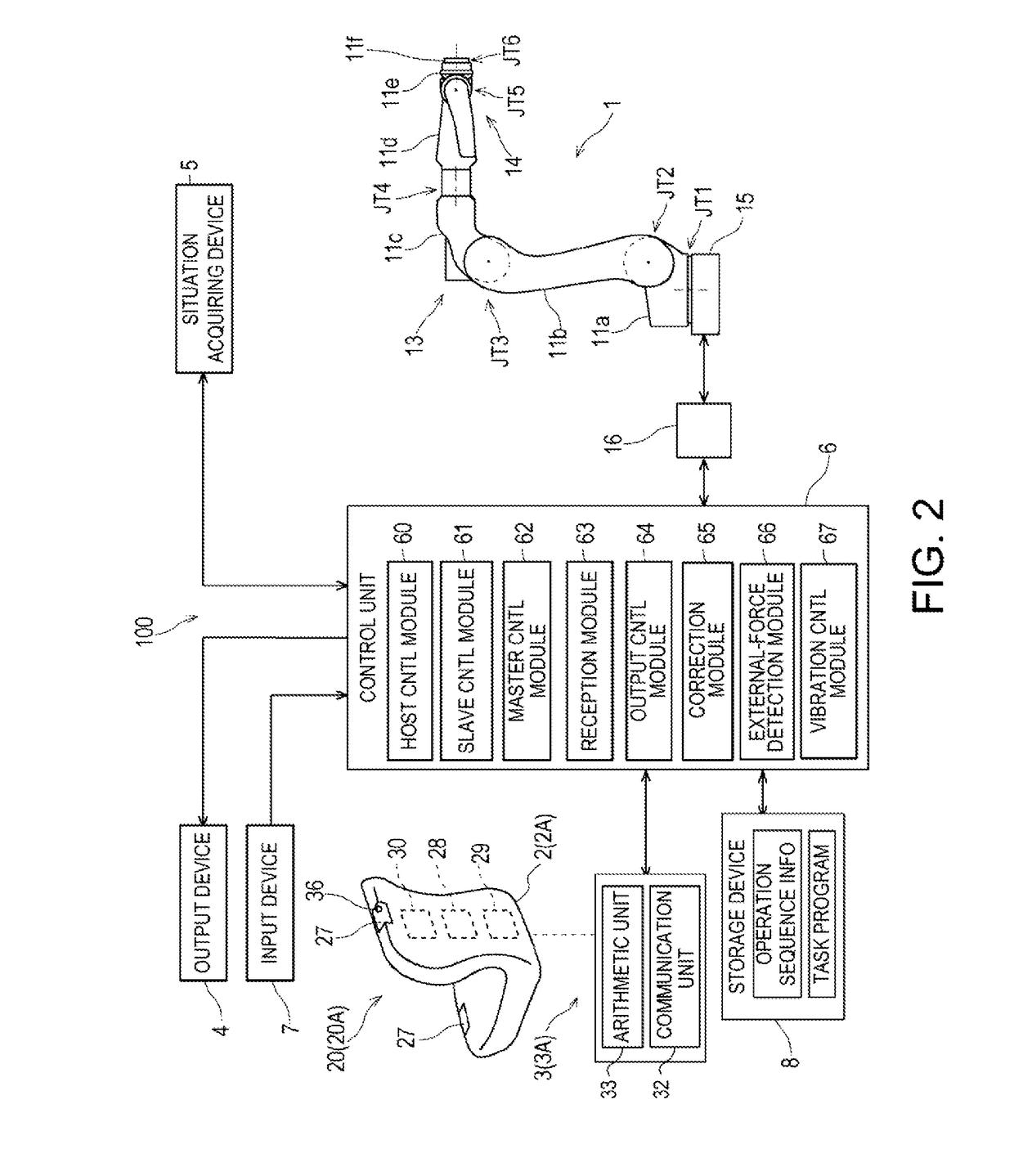
[0060]FIG. 2 is a block diagram schematically illustrating a configuration of the remote control robot system 100 provided with the master device 20 (20A) according to the first embodiment. As illustrated in FIG. 2, the master device 20A includes a master main body 2A and a manipulation receiving device 3A.

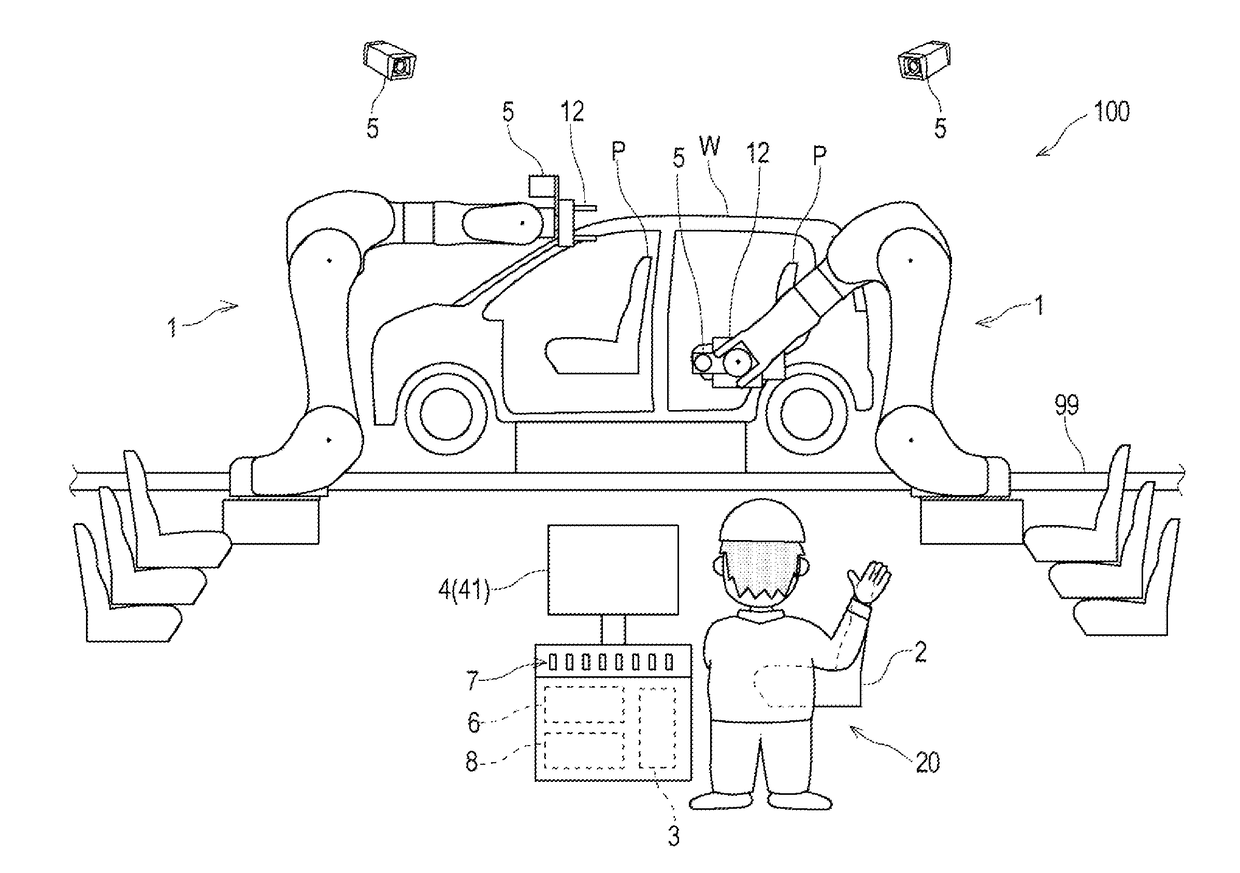
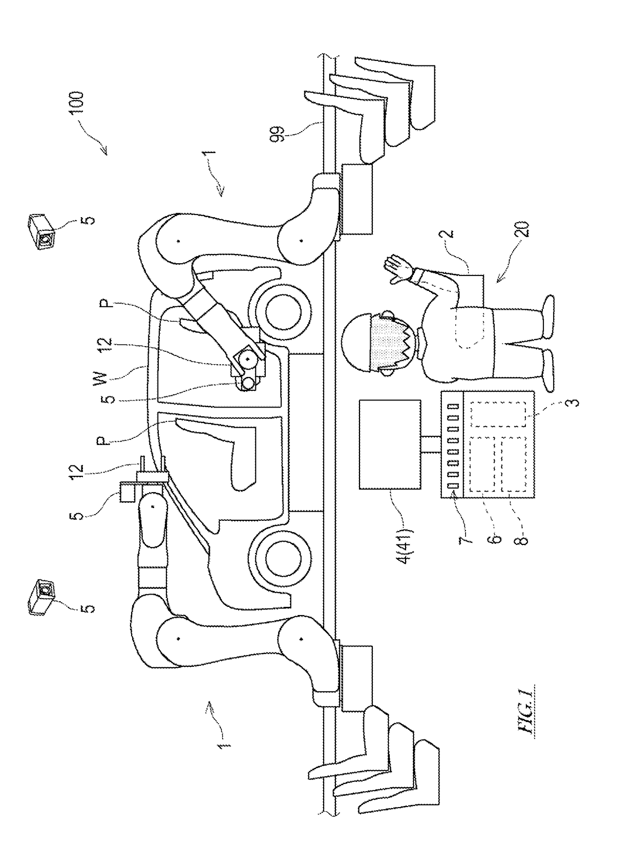
[0061]In this embodiment, an object to be handled by the slave arm 1 is a seat P of an automobile (see FIG. 1). Thus, the master main body 2 has a shape which imitates the contour of the object to be handled by the slave arm 1 (i.e., the seat P). Note that the contour of the master main body 2 is not limited to the shape same as the object, but may have a similar shape as the object. For example, for easier manipulation by the operator, the contour of the master main body 2 may be smaller than the object and may have the similar shape as the object.

[0062]As for the master main body 2, if its contour corresponds to the contour of the object to be handled by the slave arm 1, an inte...

second embodiment

[0078]FIG. 4 is a block diagram schematically illustrating a configuration of the remote control robot system 100 provided with the master device 20 (20B) according to a second embodiment. As illustrated in FIG. 4, the master device 20B according to this embodiment includes a master main body 2B and a manipulation receiving device 3B. The configuration of the master main body 2B is substantially the same as that of the master main body 2A according to the first embodiment and, thus, detailed description thereof is omitted.

[0079]The manipulation receiving device 3B includes a manipulator 23 to which the master main body 2B is attached at a hand part thereof, and an arithmetic unit 24 which calculates the position and posture of the master main body 2B based on the rotational position of each joint of the manipulator 23.

[0080]The manipulator 23 is an articulated robot arm having a plurality of joints JTm1-JTm6 of which the number is the same as the slave arm 1, and is structured by se...

third embodiment

[0088]FIG. 5 is a block diagram schematically illustrating a configuration of the remote control robot system 100 provided with the master device 20 (20C) according to a third embodiment. As illustrated in FIG. 5, the master device 20C according to this embodiment includes a master main body 2C and a manipulation receiving device 3C. The configuration of the master main body 2C is substantially the same as that of the master main body 2A according to the first embodiment and, thus, detailed description thereof is omitted.

[0089]The manipulation receiving device 3C is configured as a motion capture system which captures a motion of the master main body 2C. Although various techniques are known for the motion capture system, for example, a motion capture system which is comprised of markers 34 provided at a plurality of locations on the surface of the master main body 2C, a plurality of camera devices 35 which image the markers 34, and an image-processing device 38 which processes the ...


PUM


Abstract

A remote control robot system includes a slave arm, a master main body imitating the shape of an object handled by the slave arm, a manipulation receiving device configured to receive manipulation of an operator based on the position and posture of the master main body, and a control device configured to control operation of the slave arm based on the manipulation received by the manipulation receiving device so that behavior of the object corresponds to behavior of the master main body.

Description

TECHNICAL FIELD[0001]The present disclosure relates to a remote control robot system provided with a master device and a slave arm.BACKGROUND ART[0002]Conventionally, remote control robot systems provided with a master device (i.e., a remote control device) and a slave arm which operates according to manipulation of the master device are known. As the master device, a manipulator, a control lever, a manual operation button, etc. may be used. In such remote control robot systems, some are configured so that the posture of the slave arm follows the posture of the manipulator as the master device. Patent Document 1 discloses this kind of art.[0003]In Patent Document 1, a master-slave type manipulator for medical use, which is provided with a portable arm manipulating part as the master device is disclosed. This portable arm manipulating part includes an operation table with a shoulder belt for an operator, a display provided to the operation table, and a plurality of small master arms ...

Claims


Application Information

Patent Timeline
IPC IPC(8): B25J3/00B25J13/06B23P19/04B25J19/04B25J13/08B25J9/16
CPCB25J3/00B25J13/06B23P19/04B25J19/04B25J13/088B25J9/1669B23P21/00B25J18/00G05B2219/40195G05B2219/39004G05B2219/39439G05B19/4182G05B2219/39102G05B2219/40022B25J9/1689G05B2219/40136G05B2219/40142G05B2219/40146G05B2219/40161G05B2219/40162G05B2219/40169G05B2219/40183G05B2219/40163G05B2219/40627G05B2219/39533G05B2219/40145G05B2219/40143G05B2219/40134G05B2219/40139G05B2219/35464G05B2219/40182G05B2219/39531B25J9/1674G05B2219/33007G05B2219/37297G05B2219/40387B25J3/04B25J13/025B25J9/16B25J9/1692B25J9/1682B25J9/0087B25J9/1641B25J9/1638H04N23/611B25J13/00B25J9/0084B25J9/1697B25J13/006B25J13/08Y10S901/09Y10S901/47Y10S901/08B25J9/161B25J9/1664B25J19/023B25J9/1633B23Q15/12B25J9/1628B25J13/02B25J9/163Y10S901/03Y10S901/27B25J11/008Y10S901/41B25J13/003B25J13/065G06F3/017B25J13/084Y10S901/10Y10S901/46H04N7/181Y10S901/02B25J9/1653B25J9/1612B25J19/028B25J9/1602B25J13/085B25J13/087A61B34/32A61B34/37G06T7/62G06T7/70B25J9/0081B25J9/1646B23P21/002
Inventor HASHIMOTO, YASUHIKOSHIMOMURA, NOBUYASUMAEHARA, TSUYOSHIKAMON, MASAYUKI
Owner KAWASAKI HEAVY IND LTD
Why Eureka
Try Eureka