
Object storage, handling, and retrieving system and method

a technology for retrieving systems and objects, applied in the field of object storage, handling and retrieving systems and methods, can solve the problems of impracticality of such systems, low storage density of such systems, and congestion among load handlers on the top of the grid, so as to reduce the impact of congestion on load handling devices

Active Publication Date: 2020-11-03
OCADO INNOVATION
View PDF27 Cites 9 Cited by
  • Summary
  • Abstract
  • Description
  • Claims
  • Application Information

AI Technical Summary

Benefits of technology

[0038]Preferably there are a number of drop off points at which the or each container may be transferred from the storage system to the sequencing and storage portion. The ability to drop multiple containers off at a given time at a given sequencing and storage portion further reduces the impact of congestion in load handling devices on the grid.
[0040]Advantageously this reduces load handling device congestion on the grid.
[0051]In this way, the order of arrival of the container or containers at the sequencing and storage portion of the object handling system is not important, the selecting means and control utility acting on containers within the sequencing and storage portion ensures the correct container arrives at the workstation port at the correct time in the correct order, with a greatly reduced number of lifting operations required by the load handling devices.

Problems solved by technology

It will be appreciated, however, that the need to provide aisle space to access the products means that the storage density of such systems is relatively low.
An additional disadvantage of the system described above results from the requirement that to compile a customer order comprising a number of objects in to at least one delivery may require several aisles to be accessed for a single order.
This becomes a particular issue if the volume of orders to be compiled is high.
Whilst this method, to be described in more detail below, offers the ability to access all parts of the storage system and move all objects via load handling devices to all work stations, this may cause congestion among the load handlers on top of the grid.
The cost of such systems are, however, impractical in many situations and they have mainly been commercialised for the storage and handling of large shipping containers.
Furthermore, the system is not well adapted for the selection of a single container from a multi-product stack.
The use of single-product stacks in such cases can be impractical, since a very large floor area would be required to accommodate all of the stacks required.
Furthermore, it can be desirable only to store small quantities of some items, such as perishables or infrequently-ordered goods, making single-product stacks an inefficient solution.
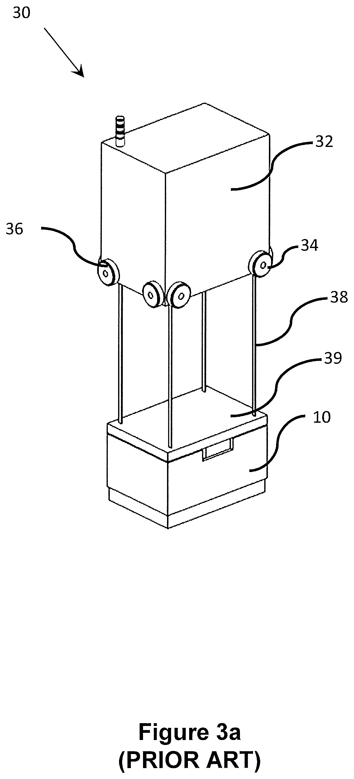
However, there are some drawbacks with such a system, which all result from the above-described digging operation that must be performed when a target bin 10b is not at the top of a stack 12.
The digging process consumes a large part of the operating time of the load handling devices 30, reducing the efficiency and increasing the cost of the system, because it is necessary to provide multiple load handling devices 30 to avoid delays.
The digging operation is relatively slow, and it can take many minutes to access a target bin 10b that is situated towards the bottom of a stack 12.
As a result, the system cannot react quickly to changes in demand without significant loss of productivity.
However, this approach becomes limited in applications in which products are picked to assemble orders that consist of a relatively large number of products selected from a very large number of product lines, because it is always likely that a small number of comparatively rarely-ordered products, requiring a time-consuming digging operation, will be present in each order.
It is a disadvantage of the systems described above that fast moving or frequently accessed items stored within containers in the storage system must be continually removed and replaced by the load handling devices.
This leads to excessive over use of the load handling devices and reduces efficiency.

Method used


Image

  • Object storage, handling, and retrieving system and method
  • Object storage, handling, and retrieving system and method
  • Object storage, handling, and retrieving system and method

Examples


first embodiment

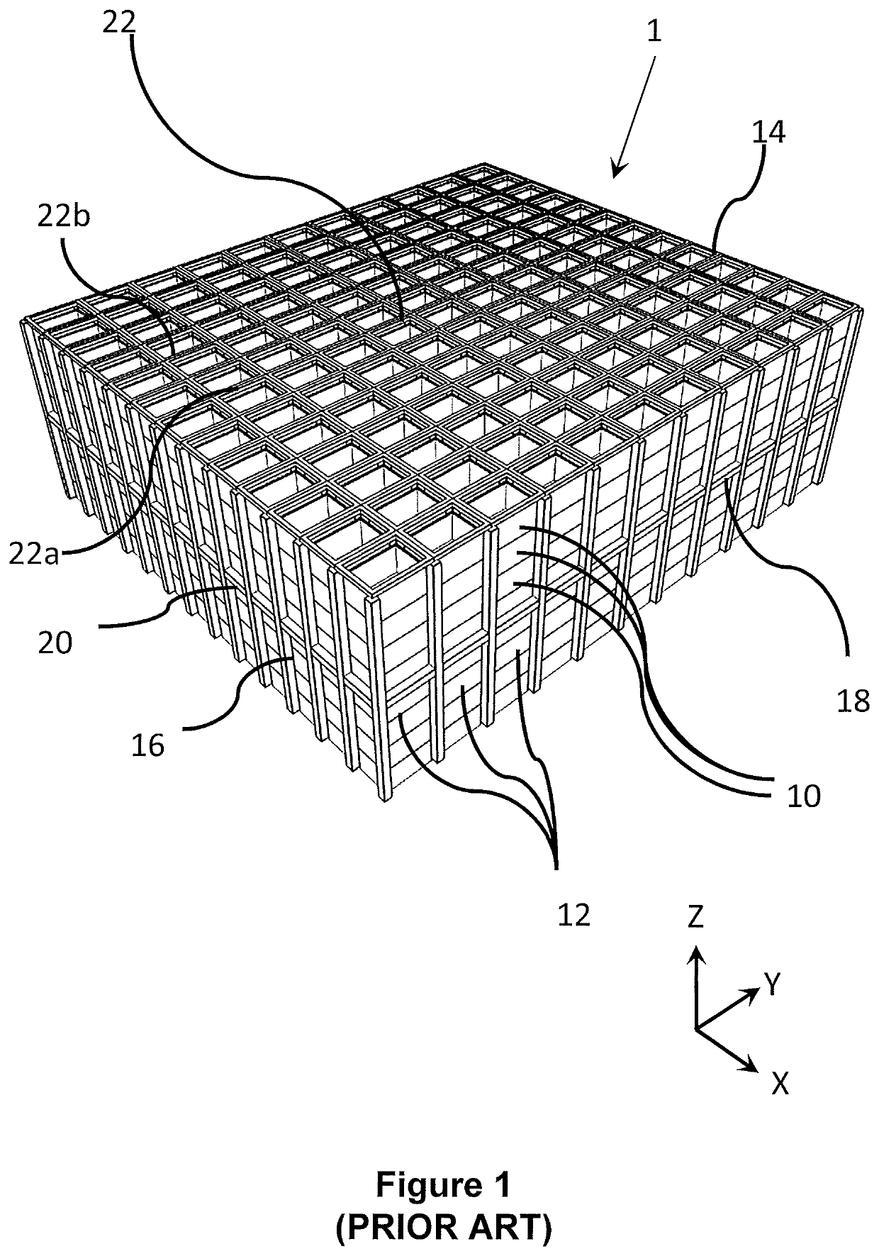
[0076]FIG. 5a is a perspective view of a sequencing and storage portion of an object handling, storage and retrieval system 100 according to the present invention. The storage system 100 is generally similar to the known system described above with reference to FIGS. 1 to 4, and comprises a plurality of storage containers or bins 10 stacked on top of one another to form a plurality of stacks 12. The stacks 12 are arranged within a frame structure 14.

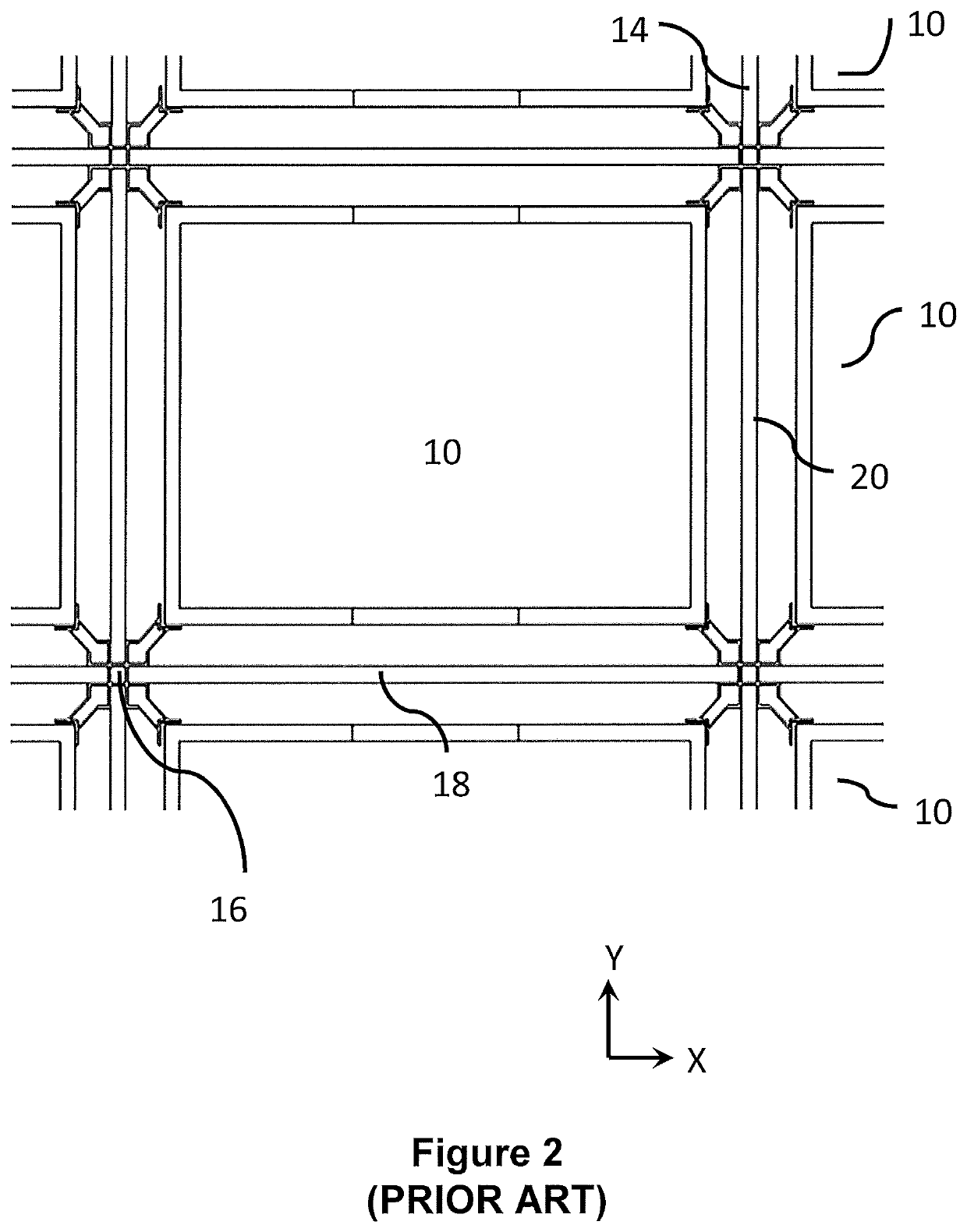
[0077]The frame structure 14 comprises a plurality of upright members 16 that extend in the Z direction and support horizontal members 18, 20. A first set of parallel horizontal members 18, arranged in the X direction, is disposed perpendicular to a second set of parallel horizontal members 20 (not shown in FIG. 5), arranged in the Y direction. The horizontal members 18, 20 form a plurality of horizontal grid structures supported by the upright members 16. The bins 10 are stacked between the members 16, 18, 20 of the frame structure 14, ...

second embodiment

[0085]the invention is described with reference to FIGS. 6a, 6b and 7 of the accompanying diagrammatic drawings.

[0086]FIG. 6a shows the framework 14 of the storage system 100 located adjacent a sequencing and storage portion 145 in accordance with a further form of the invention. As shown in FIG. 6a, a frame 150 is located between the storage system 100 and the workstation 120. The frame 150 comprises a track 160 on which storage containers 10 are located. As further shown in FIGS. 6a and 6b, the frame 150 of the second embodiment comprises a track 160 having container locating positions 155 thereon.

[0087]In use, load handling devices 30 operable on the storage system 100 locate and lift the target container 10 from a stack 12. The load handling device 30 transports the container 10 to a drop off point 171 above the frame 150 of the sequencing and storage portion 145. Once in position above the frame 150, the load handling device lowers the storage container 10 into a position on th...

fourth embodiment

[0096]FIGS. 9a, 9b, 9c, and 9d show the invention in which the sequencing and storage portion 145 of the storage system 100 comprises a frame 250, the frame comprising a track 260 on which vehicles 270 are driven. The vehicles 270 comprise temporary storage locations 240 on which containers 10 may be stored prior to movement to a workstation 120. The frame 250 and the associated track and vehicles enable a computer controlled utility to sequence the arrival of the containers 10 at the workstation 120 irrespective of the order in which the containers arrive at the storage and sequencing portion from the storage system 100. As shown in FIG. 9b, additional storage locations 240′ are provided adjacent the top surface of the frame, the storage locations 240 and 240′ enabling fast moving or frequently required containers 10 to be positioned close to the workstations 120 to reduce the number of times such containers 10 need to be lifted by load handling devices 30 from the storage system 1...


PUM


Abstract

An object handling and retrieving system and method are described. A storage system is described suitable for storing multiple product lines in an automated warehouse environment. The storage system includes a plurality of load handling devices disposed above a frame and independently moveable to access different stacks. The load handling device can retrieve and transport a target container to a sequencing and temporary storage portion having a sorting frame for taking delivery of the target container and moving it to an output port of the sorting frame.

Description

[0001]The present application hereby incorporates by reference U.S. Pat. No. 7,861,844, and PCT Patent Publication Numbers WO / 2013 / 167907 and WO / 2015 / 019055. The content of these applications and publications is hereby considered to be included in the present application.[0002]The present invention relates to storage systems and methods for retrieving units from a storage system. In particular, but not exclusively, the invention relates to a robotic system for handling bins in a store comprising a grid of stacked units.[0003]The present application claims priority from UK Patent application number GB1509921.1 filed on 8 Jun. 2015 the content of which is incorporated by reference.BACKGROUND TO THE INVENTION[0004]Some commercial and industrial activities require systems that enable the storage and retrieval of a large number of different products. One known system for the storage and retrieval of items in multiple product lines involves arranging storage bins or containers on rows of ...

Claims


Application Information

Patent Timeline
Patent Type & Authority Patents(United States)
IPC IPC(8): B65G1/04B65G1/137
CPCB65G1/1378B65G1/0464B65G1/04B65G1/1373B65G2201/0235B65G1/0485
Inventor INGRAM-TEDD, ANDREW JOHNLINDBO, LARS SVERKER TUREKAROLINCZAK, PAWEL
Owner OCADO INNOVATION
Learn More