Recording apparatus

Active Publication Date: 2018-08-30
SEIKO EPSON CORP
View PDF2 Cites 0 Cited by
  • Summary
  • Abstract
  • Description
  • Claims
  • Application Information

AI Technical Summary

Benefits of technology

[0007]An advantage of some aspects of the invention is to obtain a configuration capable of maintaining a transmission state of a drive force

Problems solved by technology

When bending is formed in the medium between the intermediate roller and the transport roller, the torque increases and the surface pressure increases when driving the intermediate roller and the reverse rotation driving amount which is necessary for causing the surface pressure to be lost also incr

Method used


Image

  • Recording apparatus
  • Recording apparatus
  • Recording apparatus

Examples


first example

Outline of Printer

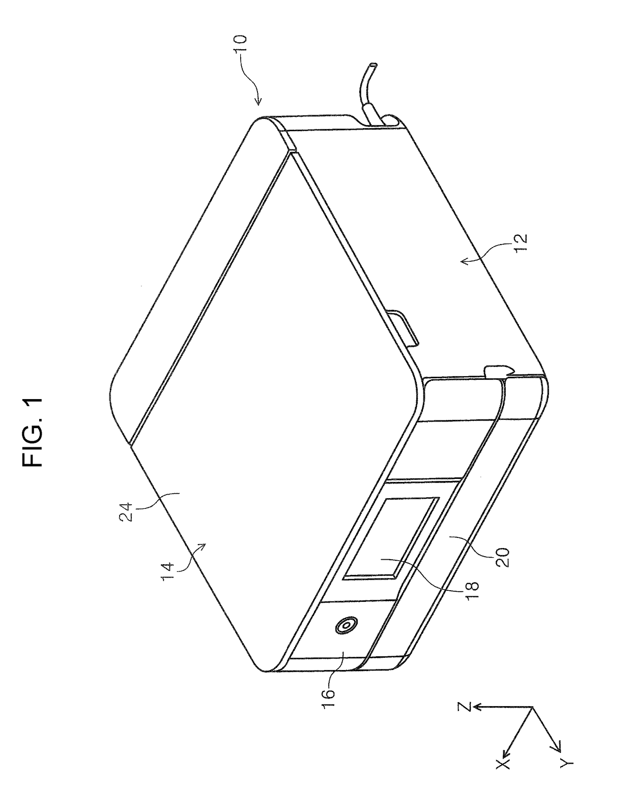
[0079]A description will be given of the overall configuration of the printer 10 with reference to FIG. 1. The printer 10 is configured as an ink jet printer as an example of a recording apparatus. The printer 10 is configured as a multifunction device which is provided with an apparatus main body 12 and a scanner portion 14. An operation unit 16 is provided on the apparatus front side of the apparatus main body 12 to be capable of rotationally moving with respect to the apparatus main body 12. A display unit 18 such as a display panel is provided on the operation unit 16.

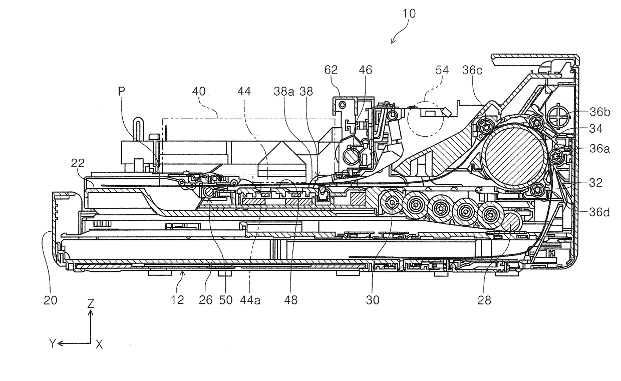
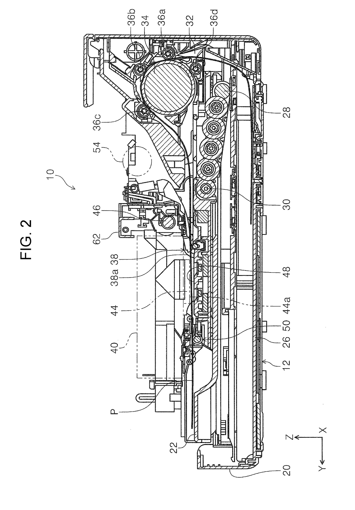
[0080]A cover 20 is disposed under the operation unit 16 on the apparatus front side of the apparatus main body 12. A paper output tray 22 is provided in the apparatus main body 12. The paper output tray 22 is configured to be capable of switching between a state of being housed inside the apparatus main body 12 (FIG. 2) and a state of being opened to the apparatus front side of the apparatus main...

modification example

[0183](1) In the present example, in the regulating member 64, a configuration is adopted in which the top surface of the first regulating portion 64c is used in the regulation of the regulated portion 80a in the first meshing state and the bottom surface of the second regulating portion 64e is used in the regulation of the regulated portion 80a in the second meshing state; however, instead of this configuration, the bottom surface of the first regulating portion 64c may be used in the regulation of the regulated portion 80a in the first meshing state, the top surface of the second regulating portion 64e may be used in the regulation of the regulated portion 80a in the second meshing state, and further, the number of driving targets of the drive motor 54 may be increased using the bottom surface of the first regulating portion 64c and the top surface of the second regulating portion 64e in addition to the top surface of the first regulating portion 64c and the bottom surface of the ...


PUM


Abstract

A recording apparatus includes a switching mechanism which switches a motive force transmission state from a motive force source, includes a sun gear which is driven by the motive force source, a planet gear which performs planetary motion around the sun gear, a rotational movement member which causes the planet gear to perform planetary motion by rotationally moving, and a regulating member which engages with a regulated portion which is provided in the rotational movement member to restrict the rotational movement of the rotational movement member.

Description

BACKGROUND1. Technical Field[0001]The present invention relates to a recording apparatus which performs recording on a medium.2. Related Art[0002]In a printer which is an example of the recording apparatus, in order to suppress an increase in the cost and an increase in the size of the apparatus, a configuration is adopted in which a plurality of driving targets are driven by a shared drive source (for example, a motor). In such a printer, a switching mechanism which switches a motive force transmission state according to which of a plurality of driving targets the drive from a drive source is to be transmitted (for example, refer to JP-A-2009-274304).[0003]A motive force transmission switching device described in JP-A-2009-274304 is provided with a motive force transmission unit which is displaced between a first position and a second position and a coil spring which biases the motive force transmission unit toward the first position. The motive force transmission switching device ...

Claims


Application Information

Patent Timeline
IPC IPC(8): B41J29/38B41J2/045B41J2/165B41J13/03B41J23/02F16H1/22
CPCB41J29/38B41J2/0451B41J2/04586B41J2/16544B41J2/04551B41J13/03B41J2/16511B41J23/025F16H1/22B41J2002/16514B41J2/16508B41J2/16517B41J2/16523B41J2/16538B41J19/202B41J29/02B41J29/13F16H1/06F16H1/28
Inventor NAKANO, YOSUKETAKEUCHI, ATSUHIKOSHIRAI, TOMOKOOKAZAWA, YOSHIYUKI
Owner SEIKO EPSON CORP
Why Eureka
Try Eureka