Image recording apparatus

a technology of image recording and a camera, which is applied in the direction of printing, other printing apparatus, etc., can solve the problems of increased product size, poor usability for placing and retrieving documents on and from the glass face, and large apparatus footprint, so as to avoid the increase in the size of the apparatus, increase the height of the apparatus, and increase the footprint

Pending Publication Date: 2021-12-09
CANON KK
View PDF7 Cites 0 Cited by
  • Summary
  • Abstract
  • Description
  • Claims
  • Application Information

AI Technical Summary

Benefits of technology

[0013]According to the present invention, placement of a heating portion can be realized while avoiding increase in size of the apparatus, such as a larger footprint, increase height of the apparatus, and so forth.

Problems solved by technology

In a case of adding a heating portion to the configuration disclosed in Japanese Patent Application Publication No. 2018-130936, there is a problem in that the conveying route becomes long in the horizontal direction depending on the layout, leading to an increased product size, and, in particular, to a larger footprint of the apparatus.
Also, in a case of installing the heating portion further above in the vertical direction than the movement path of the head so as not to interfere with the movement path of the head, the position of the scanner portion disposed further above needs to be higher, resulting in poorer usability for placing and retrieving documents on and from the glass face.

Method used


Image

  • Image recording apparatus
  • Image recording apparatus
  • Image recording apparatus

Examples


first embodiment

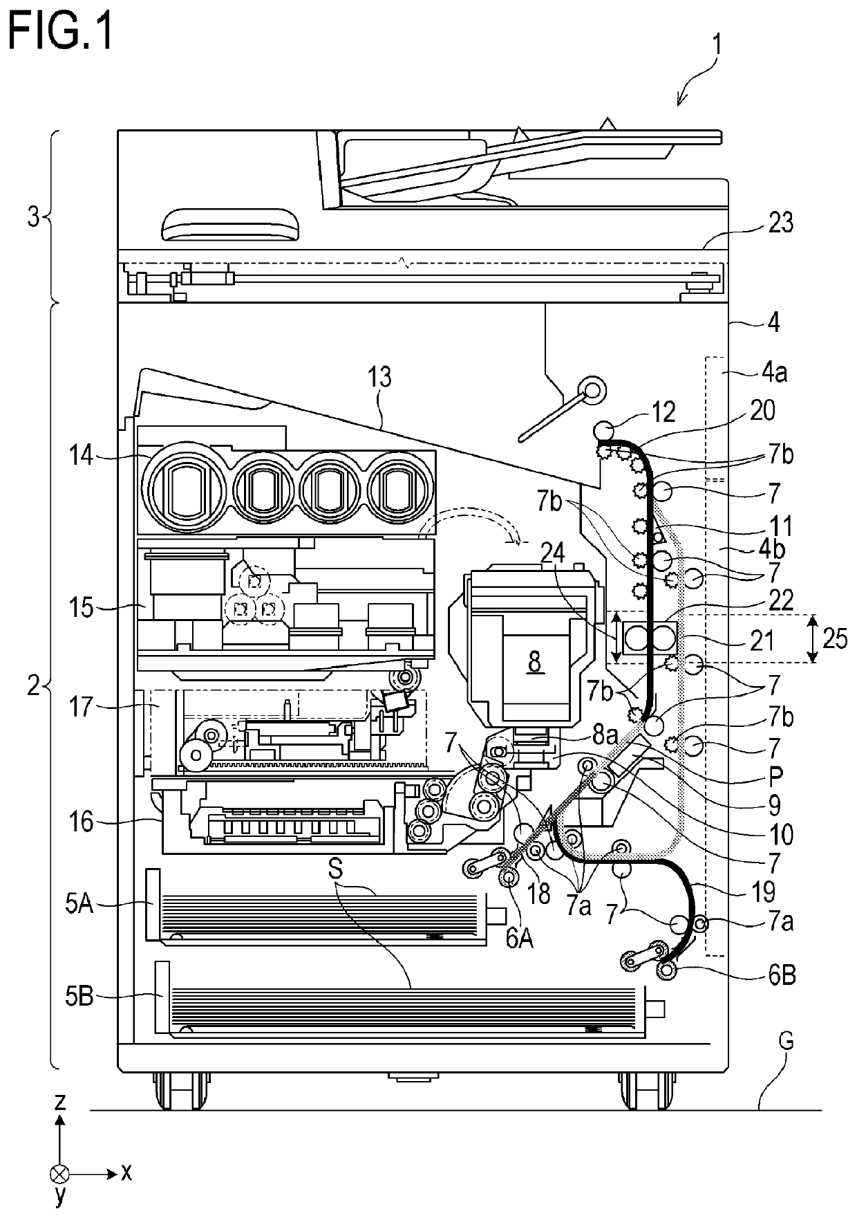
[0027]FIG. 1 is a diagram illustrating an internal configuration of an ink-jet recording apparatus 1 (hereinafter, “recording apparatus 1”) according to a first embodiment of the present invention. Hereinafter, in the Figures, the x direction represents the horizontal direction, the y direction (direction perpendicular to the plane of the Figure) represents a direction in which ejecting orifices are arrayed in a later-described recording unit 8, and the z direction represents the vertical direction.

[0028]The recording apparatus 1 is a multi-function printer (image recording apparatus) that is provided with a print portion 2 serving as an image recording portion (image recording device) and a scanner portion 3 serving as an image reading portion (image reading device). The recording apparatus 1 is capable of executing various types of processing relating to recording operations and reading operations, independently by the print portion 2 and the scanner portion 3, or by collaboration...

second embodiment

[0084]FIG. 10 is a diagram illustrating an internal configuration of a recording apparatus 1b according to a second embodiment of the present invention. In the second embodiment, configurations that are in common with the first embodiment are denoted by the same signs, and description thereof will be omitted. Items that are not described in particular in the second embodiment are the same as in the first embodiment.

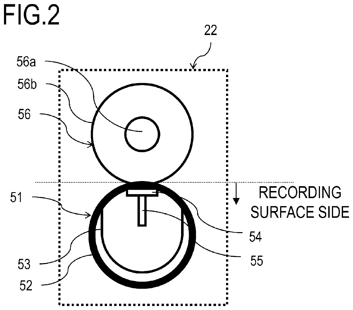
[0085]In the recording apparatus 1 according to the first embodiment, the second conveying path 21 is provided as a return conveying path in duplex recording, but the configuration of the conveying paths is not limited to this. For example, the second conveying path 21 may be a route that branches off from the first conveying path 20 between the recording region P and the heating unit 22, and merges with the first conveying path 20 between the heating unit 22 and the discharge roller 12, as in the recording apparatus 1b according to the second embodiment, as illustrated i...

third embodiment

[0086]FIG. 11 is a diagram illustrating an internal configuration of a recording apparatus 1c according to a third embodiment of the present invention. In the third embodiment, configurations that are in common with the first and second embodiments are denoted by the same signs, and description thereof will be omitted. Items that are not described in particular in the third embodiment are the same as in the first and second embodiments.

[0087]The recording apparatus 1 according to the first embodiment has the two recording medium accommodation portions of the first cassette 5A and the second cassette 5B, but the apparatus configuration is not limited to this. For example, the number of cassettes may be just one, as in the recording apparatus 1c according to the third embodiment illustrated in FIG. 11. Conversely, greater number cassettes, such as a third cassette and a fourth cassette, may be provided. A recording apparatus may also be made that does not include cassettes as part of ...


PUM


Abstract

An image recording apparatus includes a recording portion that records an image on a recording medium, a heating portion that heats the recording medium on which recording has been performed by the recording portion, a discharge portion that discharges the recording medium on which recording has been performed by the recording portion, a first conveying path for conveying the recording medium from the recording portion to the discharge portion via the heating portion, and a second conveying path for conveying the recording medium from the recording portion to the discharge portion without passing through the heating portion. In a first section in which the heating portion is disposed on the first conveying path, the recording medium is guided in a direction substantially perpendicular to an installation face of the image recording apparatus. The second conveying path has a second section that is parallel to the first section.

Description

BACKGROUND OF THE INVENTIONField of the Invention[0001]The present invention relates to an ink-jet-system image recording apparatus, provided with a heating portion to promote drying by heating a recording medium on which ink is ejected.Description of the Related Art[0002]There conventionally is an ink-jet-system image recording apparatus equipped with a full-line ink-jet head that ejects ink. For example, Japanese Patent Application Publication No. 2018-130936 discloses an image recording apparatus of which a full-line ink-jet head is configured to be capable of moving among a recording position, a standby position, and a maintenance position. In this image recording apparatus, a discharge tray is disposed further above in the vertical direction than a movement path of the head so as not to interfere with the movement path of the head, and a conveying route is formed, which conveys recoding medium upward in the vertical direction from a recording portion to a discharge portion. Fur...

Claims


Application Information

Patent Timeline
Patent Type & Authority Applications(United States)
IPC IPC(8): B41J11/00B41J13/10
CPCB41J11/0024B41J13/103B41J11/007B41J13/0036B41J13/009B41J11/0022B41J11/002
Inventor ABE, TAKASHIISHIKAWASAEKI, TSUYOSHIKURITA, YOSHIYUKIMUKOYAMA, YUMI
Owner CANON KK
Why Eureka
Try Eureka