
Inkjet printer

a technology of inkjet printer and inkjet head, which is applied in the field of inkjet printer, can solve the problems of failure of inkjet head and the like, etc., and achieve the effects of suppressing the increase in the size of the apparatus, reducing the unevenness of the air speed, and reducing the uneven cooling of the inkjet head

Active Publication Date: 2016-06-30
RISO KAGAKU CORP
View PDF0 Cites 0 Cited by
  • Summary
  • Abstract
  • Description
  • Claims
  • Application Information

AI Technical Summary

Benefits of technology

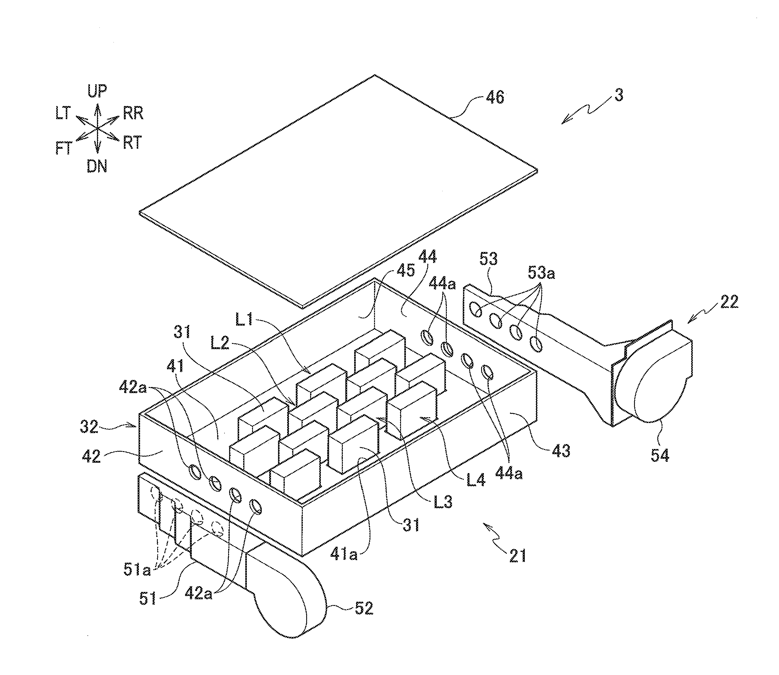
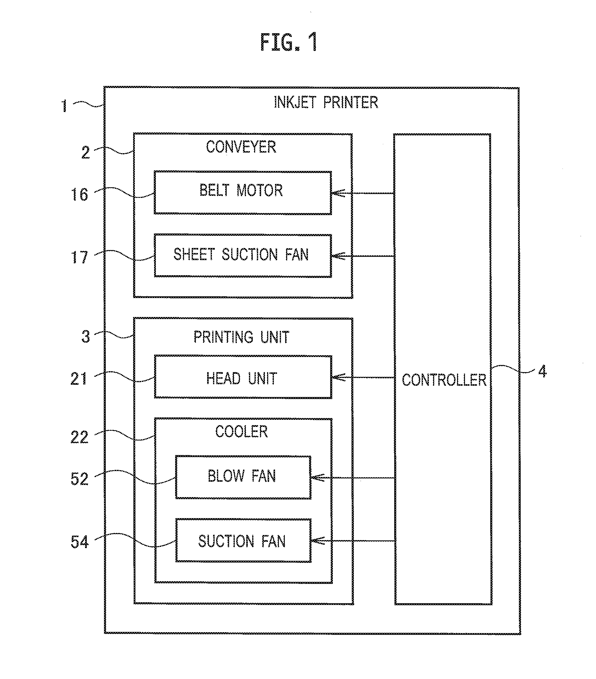
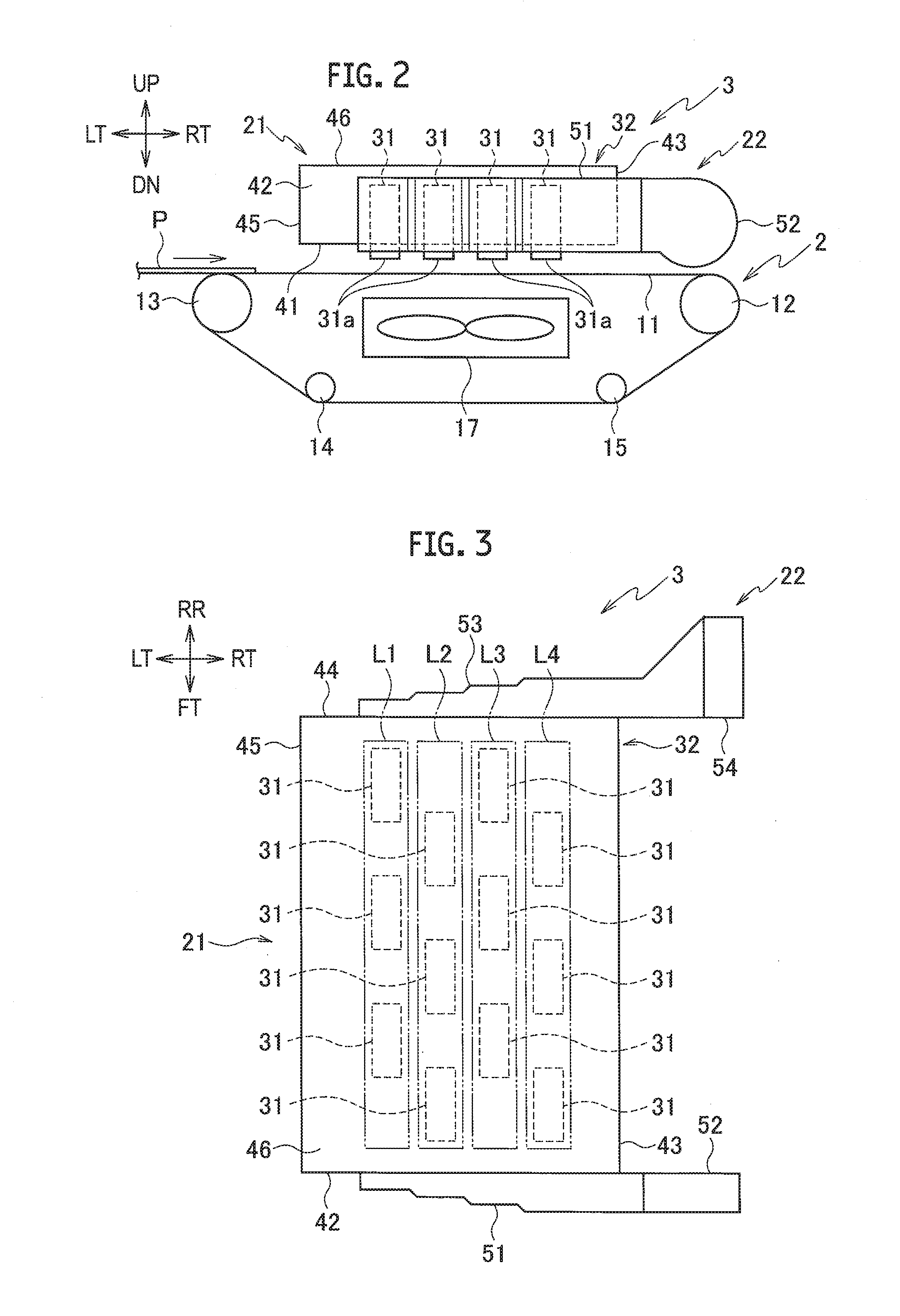
The invention aims to reduce uneven cooling of inkjet heads while preventing an increase in the size of the inkjet printer. It achieves this by designing a chamber with cross-sectional areas decreasing at the positions of the first and second ventilation holes, which results in an even distribution of cooling wind among the inkjet heads. This configuration ensures that all inkjet heads are cooled only by one fan and one chamber on each side, reducing the need for additional fans and chambers and minimizing the space required for the inkjet printer.

Problems solved by technology

A temperature increase due to this generated heat causes failures of the inkjet heads and the like.
However, this leads to an increase in an apparatus size.

Method used


Image

  • Inkjet printer
  • Inkjet printer
  • Inkjet printer

Examples


first embodiment

Modified Example of First Embodiment

[0069]Next, description is given of a modified example in which the blow chamber and the suction chamber in the aforementioned first embodiment are modified. FIG. 6 is an exploded perspective view of a printing unit in the modified example.

[0070]As illustrated in FIG. 6, the printing unit 3A in the modified example has a configuration in which the cooler 22 of the printing unit 3 in the aforementioned first embodiment is replaced by a cooler 22A. The cooler 22A has a configuration in which the blow chamber 51 is replaced by a blow chamber 51A and the suction chamber 53 is replaced by a suction chamber 53A in the cooler 22 in the first embodiment.

[0071]The blow chamber 51A includes a blow chamber main body 61 and a frame 62.

[0072]The blow chamber main body 61 has a configuration in which most of the surface of the blow chamber 51 in the first embodiment facing the side plate 42 of the head holder 32 is opened to form an opening 61a. The blow chambe...

second embodiment

[0083]Next, description is given of a second embodiment in which the printing unit of the aforementioned first embodiment is modified. FIG. 7 is an exploded perspective view of the printing unit in the second embodiment. FIG. 8 is a front view of the printing unit in the second embodiment. FIG. 9 is a rear view of the printing unit in the second embodiment.

[0084]As illustrated in FIG. 7, the printing unit 3B in the second embodiment has a configuration in which the cooler 22 of the printing unit 3 in the aforementioned first embodiment is replaced by a cooler 22B. The cooler 22B has a configuration in which the blow chamber 51 is replaced by a blow chamber 51B and the suction chamber 53 is replaced by a suction chamber 53B in the cooler 22 in the first embodiment.

[0085]As illustrated in FIGS. 7 and 8, the blow chamber 51B is formed in such a shape that the width of the blow chamber 51B in an up-down direction at the position of each of the ventilation holes 51a decreases toward the ...


PUM


Abstract

A first chamber has a plurality of first ventilation holes of a same size arranged on extended lines of a plurality of head arrays respectively. A second chamber faces the first chamber across the plurality of head arrays and has a plurality of second ventilation holes of a same size facing the plurality of first ventilation holes. Cross-sectional areas of an internal air flow passage in the first chamber at positions of the first ventilation holes decrease with an increase in a distance of the first ventilation holes from a first end of the first chamber. Cross-sectional areas of an internal air flow passage in the second chamber at positions of the second ventilation holes decrease with an increase in a distance of the second ventilation holes from a second end of the second chamber on the same side of the first end.

Description

CROSS REFERENCE TO RELATED APPLICATION[0001]This application is based upon and claims the benefit of priority from the prior Japanese Patent Application No. 2014-265089, filed on Dec. 26, 2014, the entire contents of which are incorporated herein by reference.BACKGROUND[0002]1. Technical Field[0003]The disclosure relates to an inkjet printer configured to perform printing by ejecting inks from inkjet heads.[0004]2. Related Art[0005]When inkjet heads are driven in an inkjet printer, piezoelectric elements, a drive circuit, and the like generate heat. A temperature increase due to this generated heat causes failures of the inkjet heads and the like. Accordingly, the inkjet heads need to be cooled.[0006]Japanese Patent Application Publication No. 2010-264752 proposes an inkjet printer in which two fans are arranged across head arrays each including inkjet heads aligned. In the inkjet printer, one of the fans blows a cooling wind to the inkjet heads, while the other fan sucks the coolin...

Claims


Application Information

Patent Timeline
Patent Type & Authority Applications(United States)
IPC IPC(8): B41J29/377B41J2/14
CPCB41J2/14B41J29/377
Inventor ARIMURA, EIJIRO
Owner RISO KAGAKU CORP
Learn More