Image processing apparatus and image processing method

a technology of image processing apparatus and image processing method, which is applied in the direction of filling the planer surface with attributes, closed circuit television system, instruments, etc., can solve the problems of limited mask region shape and difficulty in accurately tracing the image of the object to be protected, and achieve the effect of suppressing the increase in the size of the apparatus configuration and increasing the degree of freedom

Inactive Publication Date: 2013-01-31
JVC KENWOOD CORP A CORP OF JAPAN
View PDF4 Cites 0 Cited by
  • Summary
  • Abstract
  • Description
  • Claims
  • Application Information

AI Technical Summary

Benefits of technology

[0015]According to the image processing apparatus and the image processing method of the present invention, it is realized to increase the degree of freedom for setting a shape of a region to be subject to masking in an image while suppressing the increase in the size of apparatus configuration.

Problems solved by technology

However, in the above-described method for dividing the captured image into blocks and setting a mask region, a shape of the mask region is limited to a shape in which rectangles are combined.
Due to this, it is difficult to accurately trace an image of object to be protected.

Method used


Image

  • Image processing apparatus and image processing method
  • Image processing apparatus and image processing method
  • Image processing apparatus and image processing method

Examples


Embodiment Construction

[0027]An exemplary embodiment of the present invention will be described below with reference to the drawings.

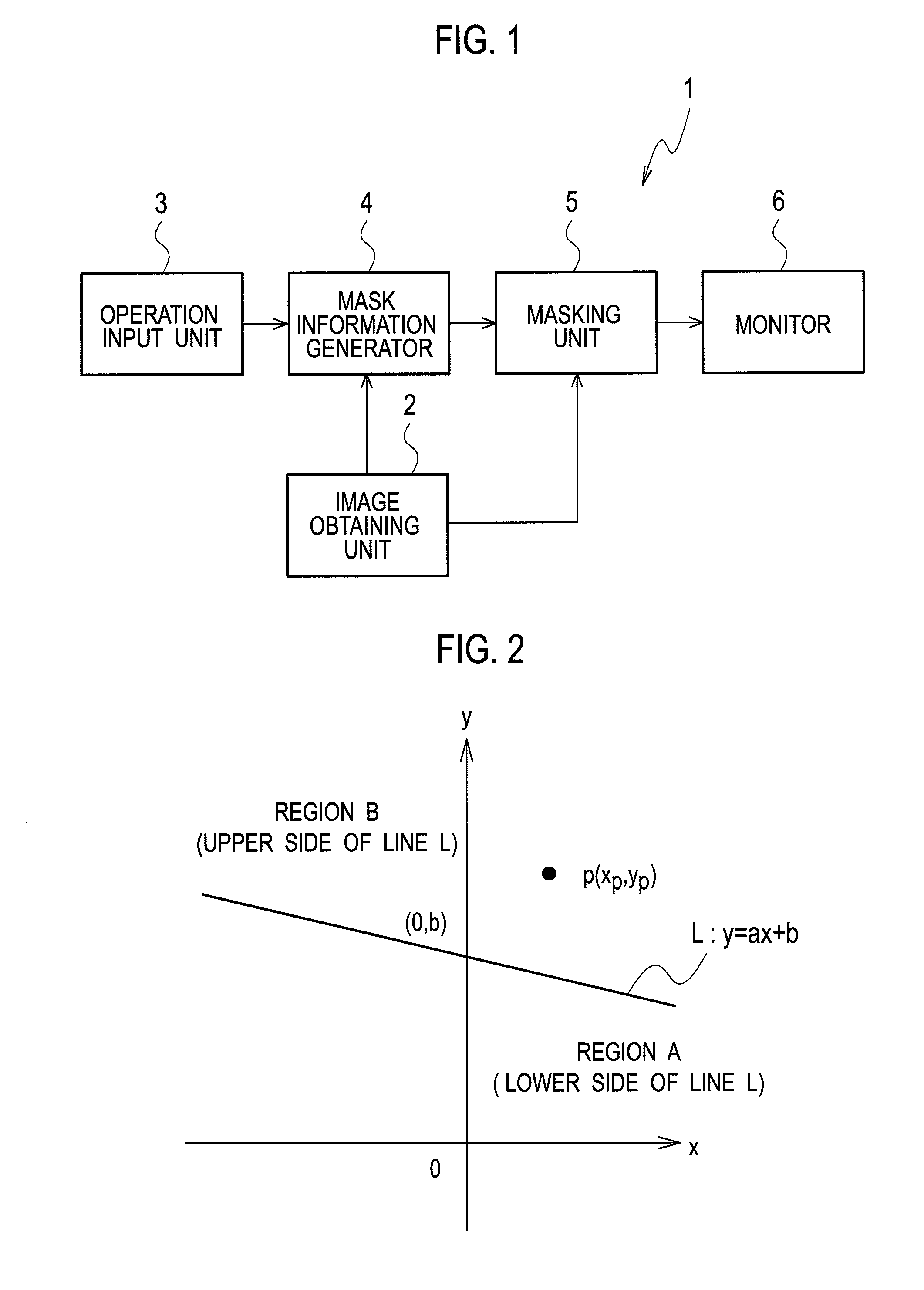
[0028]FIG. 1 is a block diagram that illustrates a configuration of an image processing apparatus according to the exemplary embodiment of the present invention. As shown in FIG. 1, an image processing apparatus 1 according to the present embodiment includes an image obtaining unit 2, an operation input unit 3, a mask information generator 4, a masking unit 5 and a monitor 6.

[0029]The image obtaining unit 2 has an image-capturing function, and outputs an image signal including a luminance signal and a color-difference signal obtained by capturing an object image and a synchronization signal thereof. The synchronization signal includes a horizontal synchronization signal, a vertical synchronization signal and a clock signal. It is noted that the image obtaining unit 2 may obtain an image signal externally captured by an image-capturing device and a synchronization signal ther...


PUM


Abstract

A mask information generator carries out the following processing: (1) defining lines which become respective sides of a polygon of which three or more points on a display screen designated by user's operation become vertices; (2) calculating a value of a coordinate in a vertical direction on each of the lines which has a value of a coordinate in a horizontal direction of each pixel designated by a counter which designates a coordinate of each pixel in an image signal based on a synchronization signal thereof; and (3) comparing a value of the coordinate designated by the counter in the vertical direction of each pixel with the calculated value of the coordinate on each of the lines, to determine whether or not each pixel in the image signal is included in a mask region which is a region within the polygon surrounded by the lines.

Description

CROSS REFERENCE TO RELATED APPLICATION[0001]This application is a Continuation of PCT Application No. PCT / JP2011 / 056339, filed on Mar. 17, 2011, and claims the priority of Japanese Patent Application No. 2010-093055, filed on Apr. 14, 2010, the content of both of which is incorporated herein by reference.BACKGROUND OF THE INVENTION[0002]1. Field of the Invention[0003]The present invention relates to an image processing apparatus and an image processing method that carry out masking with respect to a region in a part of image.[0004]2. Description of the Related Art[0005]In a case of monitoring a public space using a monitoring camera, we should take into account a matter that a private house and the like does not become public in the light of privacy protection. Because of this, a region in a part of image captured by the monitoring camera is subject to masking processing.[0006]For example, there has been known a technique in which a captured image is divided into blocks, a mask regi...

Claims


Application Information

Patent Timeline
Patent Type & Authority Applications(United States)
IPC IPC(8): G06T11/20
CPCG06T11/40H04N7/18
Inventor SATO, HIROYUKI
Owner JVC KENWOOD CORP A CORP OF JAPAN
Why Eureka
Try Eureka