Electrically-powered recirculating-ball steering gear assembly

a technology of recirculating ball and gear assembly, which is applied in the direction of gear assembly, transportation and packaging, mechanical equipment, etc., can solve problems such as complex engineering, and achieve the effects of reducing complex engineering, improving packaging, and reducing the footprin

Active Publication Date: 2018-08-30
CHINA AUTOMOTIVE SYSTEMS INC
View PDF7 Cites 23 Cited by
  • Summary
  • Abstract
  • Description
  • Claims
  • Application Information

AI Technical Summary

Benefits of technology

[0005]The invention in its broadest aspect reduces complex engineering by placing the drive systems in parallel at each end of the worm shaft. Additionally, having parallel drive systems reduces the footprint and improves packaging relative to the prior art.

Problems solved by technology

One such assembly is disclosed in U.S. Pat. No. 6,776,252, but the two drive systems in series upstream of the worm require complex engineering to provide two separate drives extending axially to the worm section.

Method used


Image

  • Electrically-powered recirculating-ball steering gear assembly
  • Electrically-powered recirculating-ball steering gear assembly
  • Electrically-powered recirculating-ball steering gear assembly

Examples


Embodiment Construction

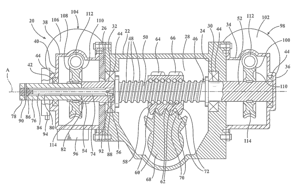
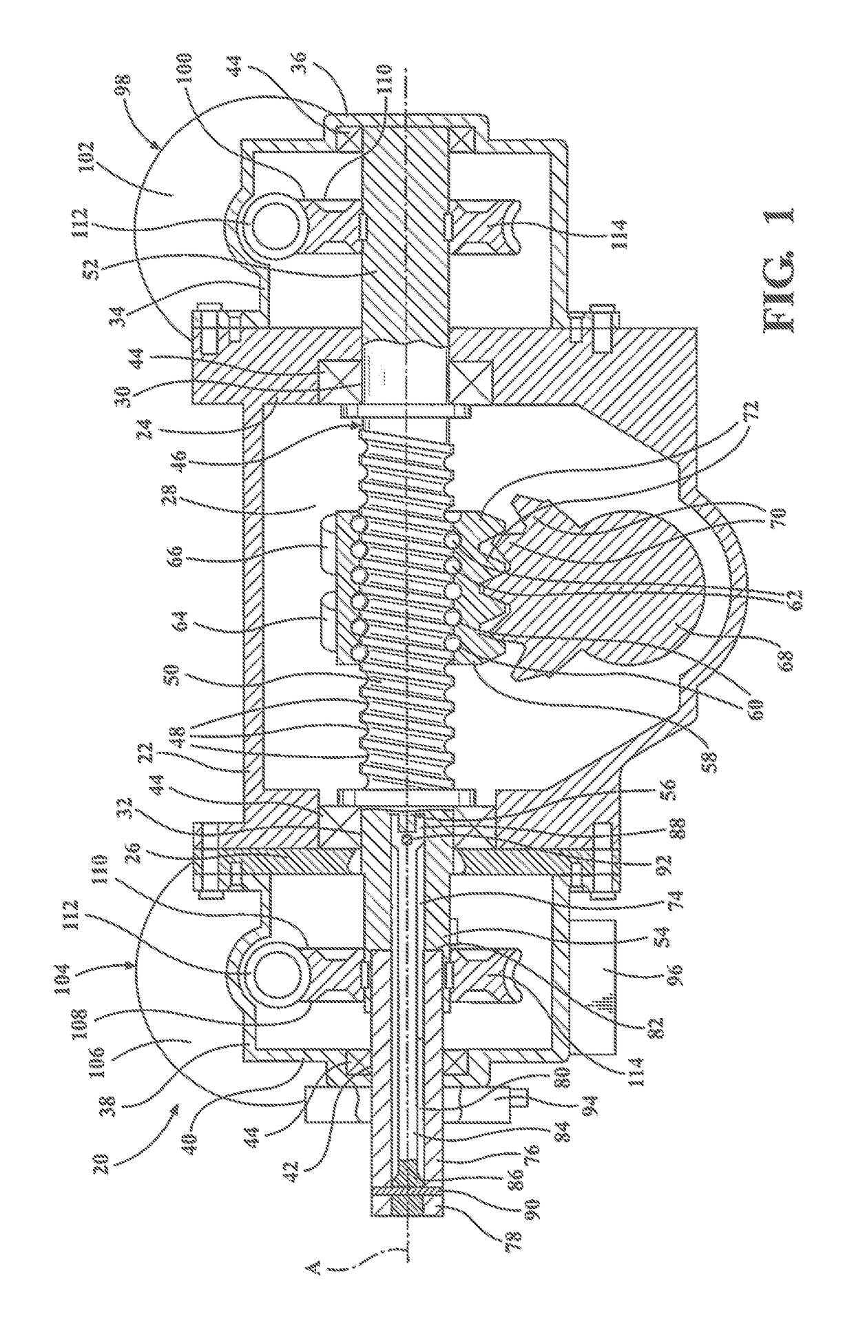
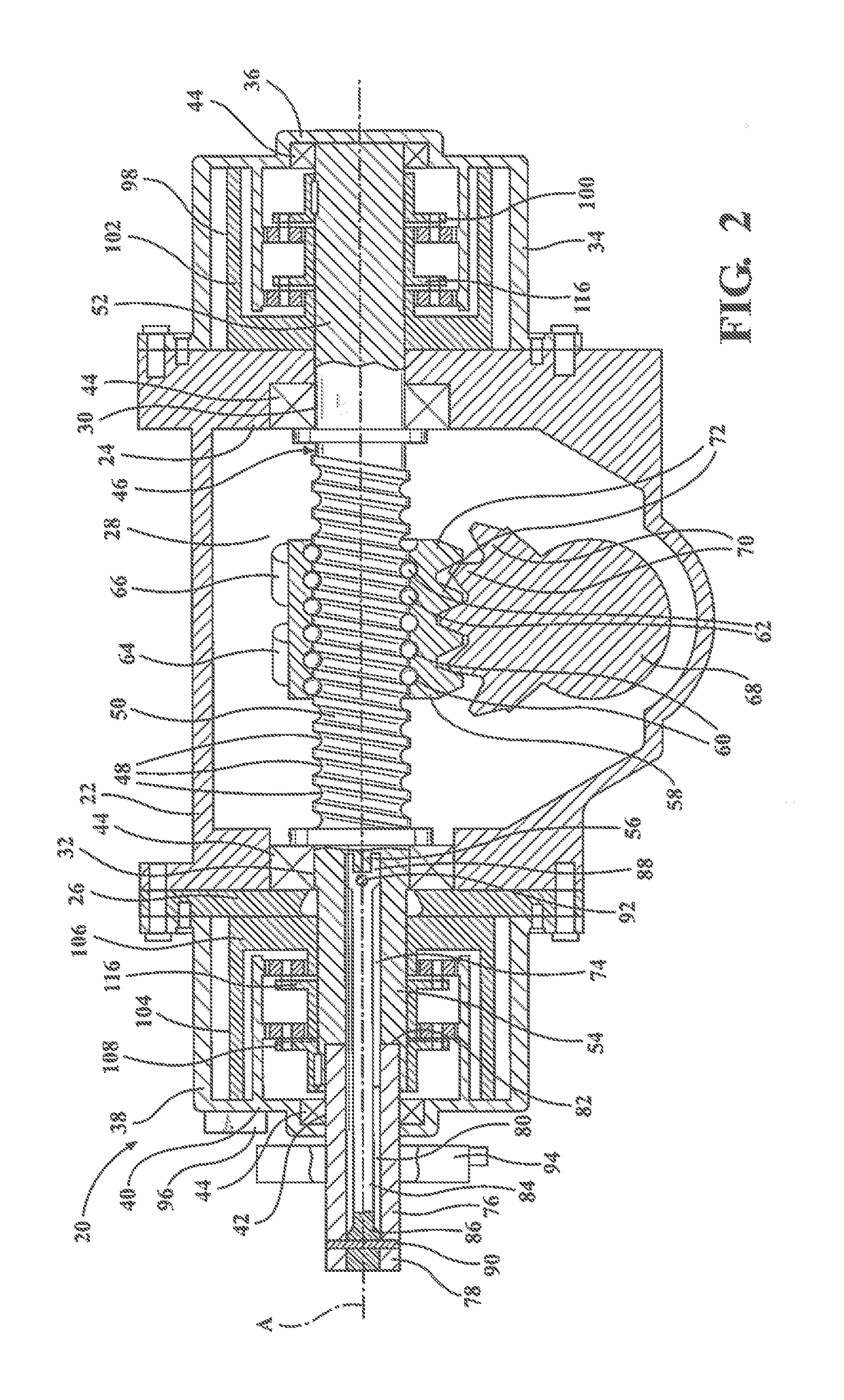
[0011]Referring to the Figures, wherein like numerals indicate corresponding parts throughout the several views. An electrically-powered recirculating-ball steering gear assembly 20 for steering a vehicle includes a main housing 22 that has a first side wall 24 and a second side wall 26 parallel and spaced from the first side wall 24 along a axis A to establish a chamber 28 therebetween.

[0012]The first side wall 24 has a first worm opening 30 disposed on the axis A. The second side wall 26 has a second worm opening 32 disposed on the axis A. A first side housing 34 is connected to the first side wall 24 around the first worm opening 30 in the main housing 22. The first side housing 34 has a protrusion 36 opposite the first worm opening 30. A second side housing 38 is connected to the main housing 22 through the second worm opening 32 and shares the second side wall 26 with the main housing 22. The second side housing 38 has an input wall 40 located parallel to and opposite the secon...


PUM


Abstract

A worm shaft (46) has a first end section (52) and a second end section (54) extending from a worm section (50). A first drive system (98) is in driving engagement with the first end section (52) of the worm shaft (46), and a second drive system (104) is in driving engagement with the second end section (54) of the worm shaft (46) for redundantly steering a vehicle. The worm section (50) of the worm shaft (46) is disposed between the first drive system (98) disposed on the first end section (52) of the worm shaft (46) and the second drive system (104) disposed on the second end section (54) of the worm shaft (46). A lost motion connection (82) is disposed between an input shaft (76) and said worm shaft (46).

Description

CROSS REFERENCE TO RELATED APPLICATION[0001]This U.S. Utility Patent Application claims the benefit of and priority to U.S. Provisional Patent Application Ser. No. 62 / 462,953 filed Feb. 24, 2017, the disclosure of which is incorporated herein by reference in its entirety.BACKGROUND OF THE INVENTION1. Field of the Invention[0002]An electrically-powered recirculating-ball steering gear assembly for steering a vehicle.2. Description of the Prior Art[0003]Such electrically-powered recirculating-ball steering gear assemblies include a worm shaft extending along an axis and having a worm groove extending helically to establish a worm section. The worm shaft has a first end section and a second end section extending from opposite ends of the worm section. A first drive system is in driving engagement with the first end section of the worm shaft and a second drive system is included for providing a steering force in response to a secondary steering input. One such assembly is disclosed in U...

Claims


Application Information

Patent Timeline
Patent Type & Authority Applications(United States)
IPC IPC(8): B62D5/04F16H25/22F16H25/20
CPCB62D5/0448F16H25/2214B62D5/0403B62D5/0421B62D5/0463F16H25/205F16H2025/209F16H2025/2075F16H2025/2031F16H2025/2087F16C1/02B62D5/04B62D5/001F16H25/2204F16H2025/2084
Inventor CAI, HAIMIANQIU, TIANYIZUO, SIQI
Owner CHINA AUTOMOTIVE SYSTEMS INC
Why Eureka
Try Eureka