Eureka AIR delivers breakthrough ideas for toughest innovation challenges, trusted by R&D personnel around the world.

Pipe stand transfer system

Active Publication Date: 2018-08-30
NAT OILWELL VARCO LP
View PDF5 Cites 4 Cited by
  • Summary
  • Abstract
  • Description
  • Claims
  • Application Information

AI Technical Summary

Benefits of technology

The patent describes a pipe handler for handling tubular members of a well system. The pipe handler comprises a mounting member for mounting the pipe handler to the well system, two arms that pivot relative to the mounting member, and a connector that joins the two arms. The guide member is attached to the second arm and guides the tubular member. The guide member has an engagement surface with a concave and convex axis. The second arm can extend or retract and is attached to the connector. The pipe handler can also include a magnet for exerting a magnetic force on the tubular member. The technical effect of this invention is to provide a reliable and efficient tool for handling tubular members in a well system.

Problems solved by technology

It is known that such movements of large sections of drill pipe may involve a variety of difficulties that, if not properly addressed by rig personnel involved in the work, may be hazardous to those personnel, both those working on the rig floor and those near the fingerboard, who may be nearly 100 feet above the rig floor.

Method used


Image

  • Pipe stand transfer system
  • Pipe stand transfer system
  • Pipe stand transfer system

Examples


Embodiment Construction

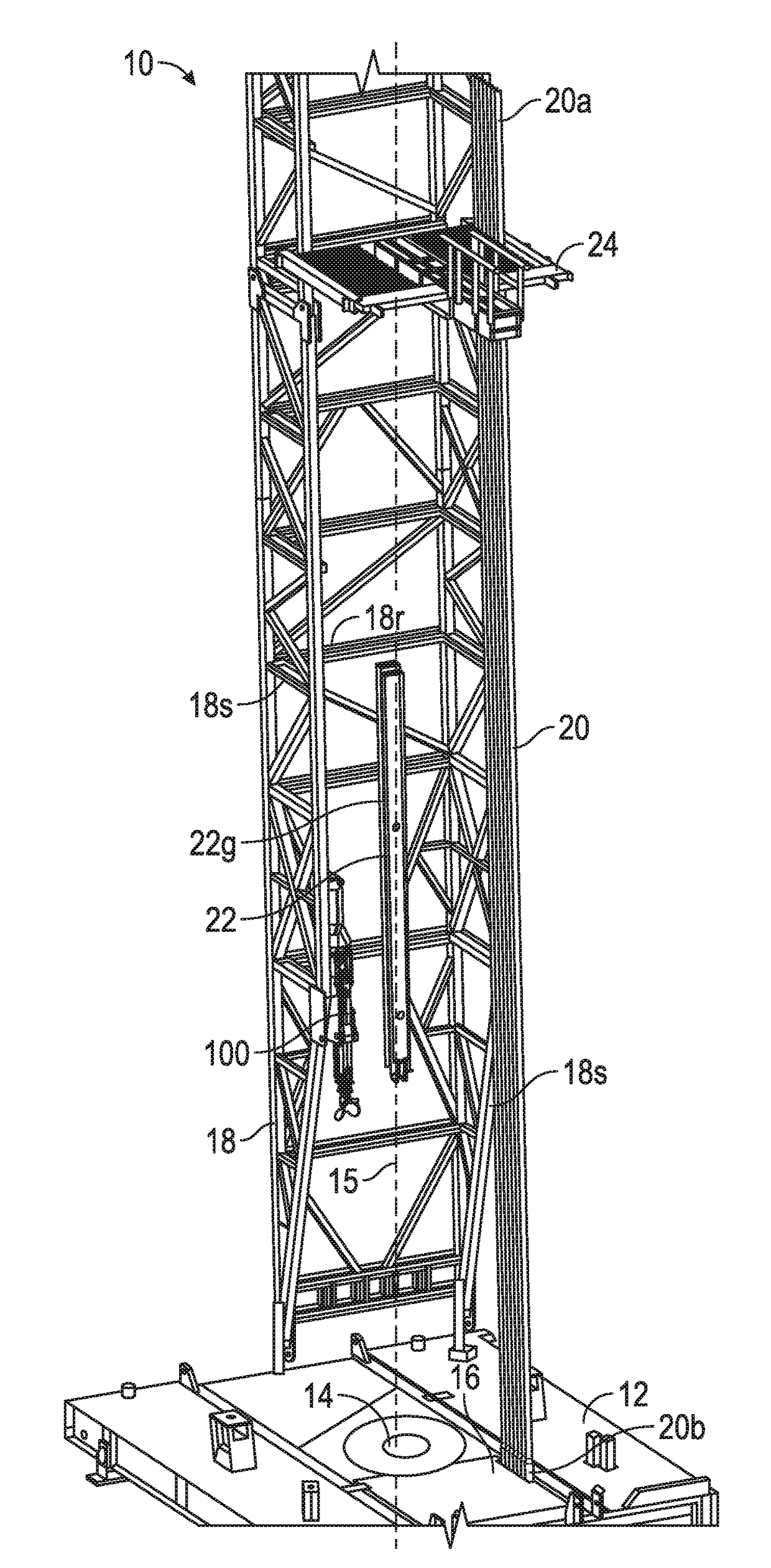
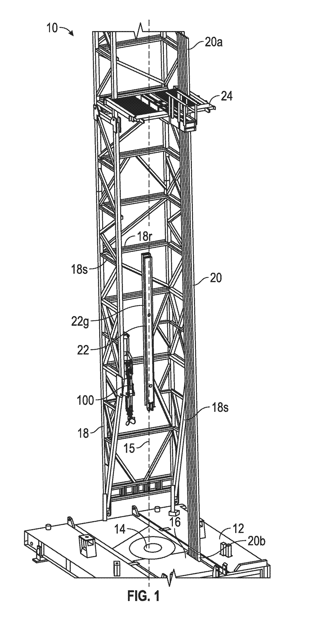
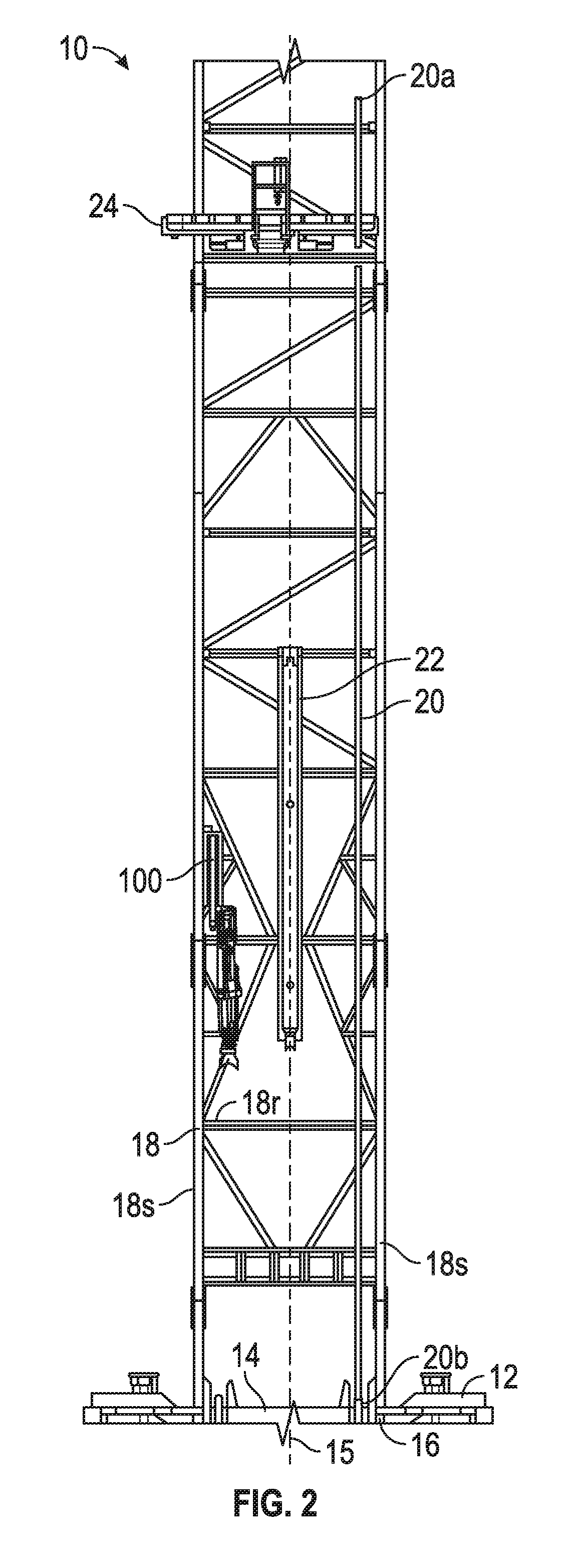
[0040]The following description is exemplary of embodiments of the disclosure. These embodiments are not to be interpreted or otherwise used as limiting the scope of the disclosure, including the claims. One skilled in the art will understand that the following description has broad application, and the discussion of any embodiment is meant only to be exemplary of that embodiment, and is not intended to suggest in any way that the scope of the disclosure, including the claims, is limited to that embodiment. The drawing figures are not necessarily to scale. Certain features and components disclosed herein may be shown exaggerated in scale or in somewhat schematic form, and some details of conventional elements may not be shown in the interest of clarity and conciseness.

[0041]The terms “including” and “comprising” are used herein, including in the claims, in an open-ended fashion, and thus should be interpreted to mean “including, but not limited to . . . .” Also, the term “couple” or...


PUM


Abstract

A pipe handler for handling tubular members of a well system includes a mounting member for mounting the pipe handler to a structure of the well system, a first arm having a first end coupled to a structure of the well system, and a second end, wherein the first arm is configured to pivot relative to the mounting member about a first axis, a second arm having a first end and a second end, a connector coupled to the second end of the first arm and the first end of the second arm, and wherein the connector is configured to rotate the second arm about a second axis and a guide member coupled to the second end of the second arm for guiding a tubular member, wherein the second arm is configured to pivot relative to the connector about a third axis.

Description

CROSS-REFERENCE TO RELATED APPLICATIONS[0001]This application claims benefit of U.S. provisional patent application Ser. No. 62 / 214,084 filed Sep. 3, 2015, and entitled “Pipe Stand Transfer System,” which is hereby incorporated herein by reference in its entirety.STATEMENT REGARDING FEDERALLY SPONSORED RESEARCH OR DEVELOPMENT[0002]Not applicable.BACKGROUND[0003]This disclosure relates generally to systems and methods for handling pipes and other elongated tubular members during well drilling, preparation, and maintenance. More particularly, this disclosure relates to systems and methods for handling elongated tubular members in a controlled manner near a drilling platform while inserting or removing the elongated tubular members from a wellbore.[0004]“Tripping” is a term of art used in drilling operations that generally refers to acts of either adding multiple joints of tubular drill pipe to, or removing multiple joints of drill pipe from, a wellbore. Oftentimes during drilling oper...

Claims


Application Information

Patent Timeline
IPC IPC(8): E21B19/14E21B15/00E21B19/24
CPCE21B19/14E21B15/00E21B19/24B25J9/045B25J9/1065B25J18/025
Inventor KEOGH, GREGORYYATER, RONALD W.RIGBY, DYLAN
Owner NAT OILWELL VARCO LP
Why Eureka
Eureka Blog
Learn More