Hydraulic power transmission device

a technology of power transmission device and piston chamber, which is applied in the direction of fluid-actuated clutches, clutches, non-mechanical actuated clutches, etc., can solve the problems of large pressure loss, long oil passage from the piston chamber to the hydraulic control body, and impact on vehicle behavior, so as to reduce the length of the oil passage leading to the pressure regulating valve from the piston chamber, reduce the size of the whole device, and reduce the effect of pressure loss

Active Publication Date: 2018-08-30
HONDA MOTOR CO LTD
View PDF2 Cites 5 Cited by
  • Summary
  • Abstract
  • Description
  • Claims
  • Application Information

AI Technical Summary

Benefits of technology

[0039]According to the hydraulic power transmission device of the present invention, as the length of the oil passage leading to the pressure regulating valve from the piston chamber can be shortened, the loss of pressure in the oil passage leading to the pressure a regulating valve from the piston chamber can be minimized. Furthermore, the hydraulic control body needed in the conventional hydraulic power transmission device and the oil passage leading to the hydraulic control body from the piston chamber also become needless. This enables to downsize the whole device and reduce manufacturing cost. If the hydraulic power transmission device of the present invention is applied to the differential of the vehicle, the impact on the vehicle behavior due to clutch dragging and the deterioration of fuel consumption rate can be prevented appropriately.
[0040]According to the hydraulic power device of the present invention, as the pressure regulating valve for adjusting pressure of the hydraulic fluid discharged from the piston chamber of the hydraulic clutch is provided adjacent to the piston chamber of the hydraulic clutch, the hydraulic control body needed for the conventional shaft core lubrication becomes needless. In addition, as the bearing is fixed due to the structure in which the bearing is sandwiched at the front and rear thereof in the axial direction, the bearing set plate that has conventionally been needed as the fixing means for the bearing and the fixing volt for the bearing set plate become needless.
[0041]In this way, as the hydraulic control body, the bearing set plate and the fixing volt for the bearing set plate become needless, the flexibility of the arrangement of the pressing load receiving member for receiving a pressing force of the piston member improves, and the pressing load receiving member and the pressing position of the piston member can be arranged at the same position in the diameter direction. Thus, the clutch series push structure, in which the pressing force of the piston member is received at the same position in the diameter direction, can be achieved.
[0042]Moreover, elimination of the offset between the pressing position and the receiving position of the clutch at the time of clutch engagement can improve the thrust efficiency of the piston member and appropriately prevent the reduction in transmission torque capacity in the hydraulic clutch.
[0043]Furthermore, if the hydraulic power transmission device of the present invention is applied to the differential of the vehicle, a desired torque can be distributed to each of the left and right driving wheels at the time of clutch engagement.

Problems solved by technology

This causes the problem that the oil passage from the piston chamber to the hydraulic control body becomes long along with a large pressure loss.
This results in clutch dragging, which might cause problems such as impacting on vehicle behavior due to transmission of a driving force to rear wheels and deteriorating fuel consumption rate.
However, the arrangement of the volt restricts the flexibility as to where to arrange the pressing load receiving member.

Method used


Image

  • Hydraulic power transmission device
  • Hydraulic power transmission device
  • Hydraulic power transmission device

Examples


Embodiment Construction

[0049]Embodiments of the present invention are hereinafter described in detail with reference to attached drawings.

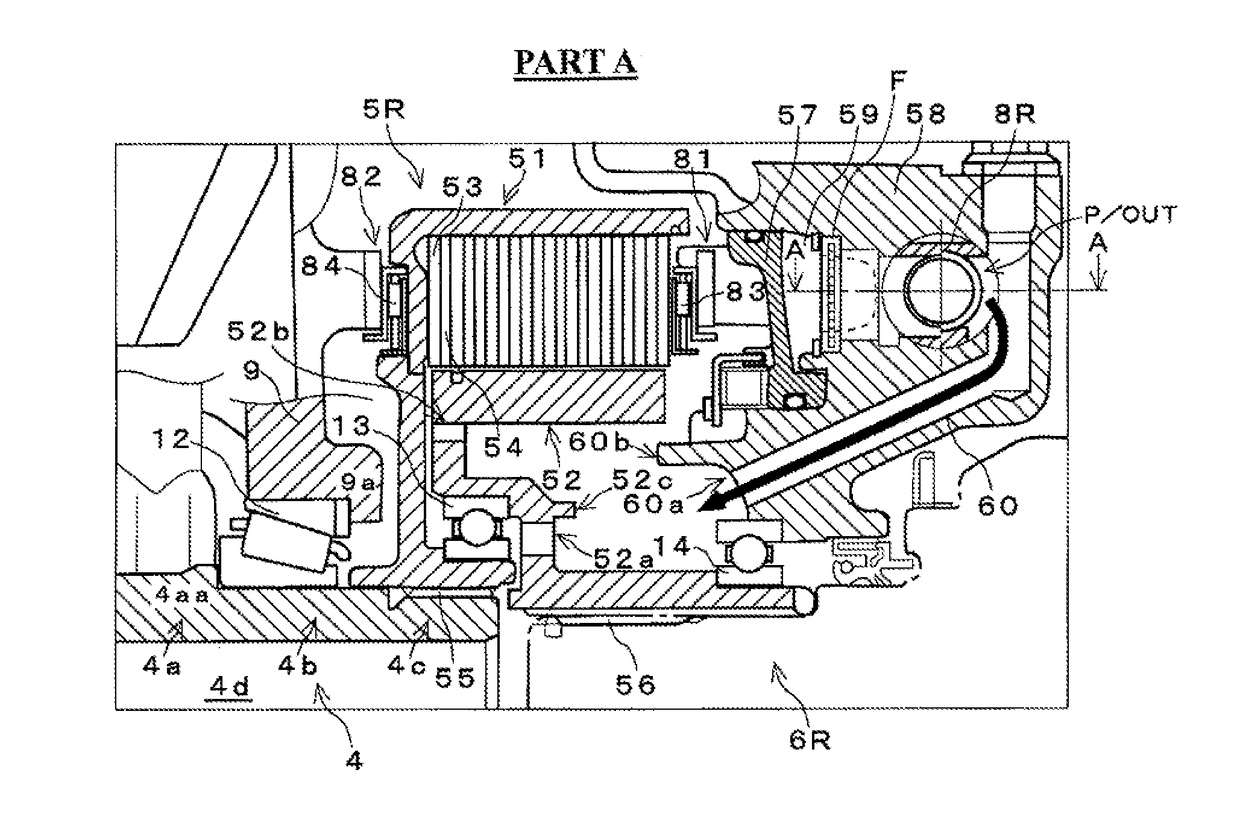
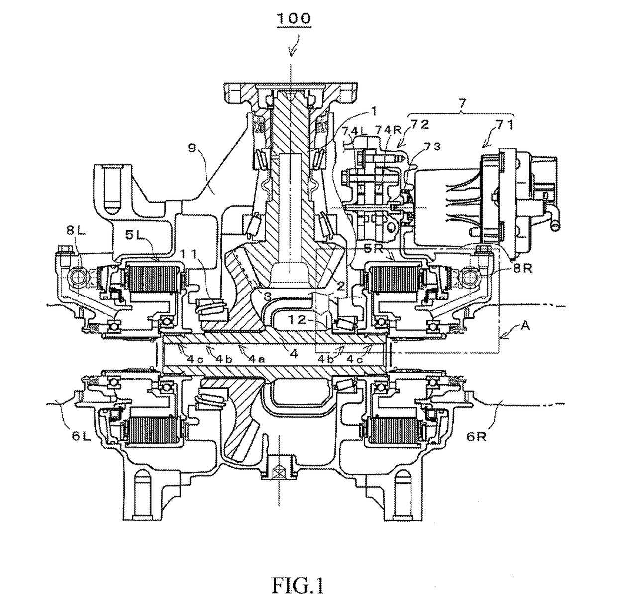
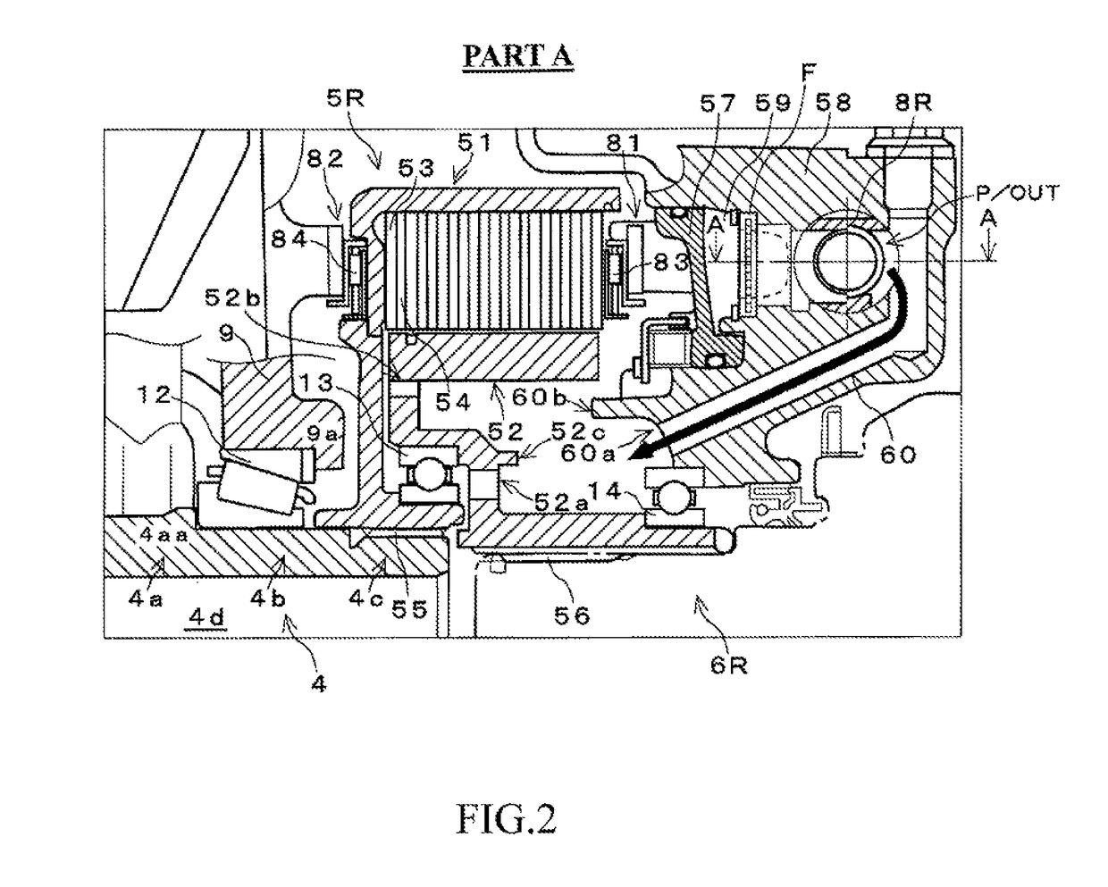
[0050]FIG. 1 is a sectional view of a main part of a hydraulic driving force transmission device 100 according to an embodiment of the present invention; FIG. 2 is an enlarged view of Part A in FIG. 1; and FIG. 3 is a perspective view for illustrating a hydraulic circuit of this hydraulic power transmission device 100. This hydraulic power transmission device 100 is configured to be a differential mechanism for distributing rotation of a drive shaft 1 to left and right wheels (not shown in the figure). A drive shaft 1 is connected to a propeller shaft, which is not shown in the figure, and a driving force from a driving source (engine), which is not shown in the figure, is transmitted to the drive shaft 1. The hydraulic power transmission device 100 includes a drive bevel gear 2 that rotates integrally with the drive shaft 1, a driven bevel gear 3 that meshes with the d...


PUM


Abstract

Provided is a hydraulic power transmission device enabling to minimize a pressure loss in an oil passage downstream from a piston chamber of a hydraulic clutch, and to properly prevent reduction in transmission torque capacity in the hydraulic clutch. Left and right pressure regulating valves (8L, 8R) regulating pressure of oil flowing out from piston chambers (59L, 59R) of left and right clutch devices (5L, 5R) are arranged adjacent to a downstream of the piston chamber (59). This can shorten an oil passage from the piston chamber (59) to the pressure regulating valve (8) and minimize pressure loss in the oil passage. Due to better flexibility of arrangement of the pressing load receiving member (82) receiving a pressing force (thrust) of the piston member (57), thrust efficiency of the hydraulic piston (57) improves to properly prevent reduction in transmission torque capacity in the hydraulic clutch (5).

Description

TECHNICAL FIELD[0001]The present invention relates to a hydraulic power transmission device including a hydraulic clutch. More specifically, a hydraulic piston presses friction materials to engage a clutch whereby the hydraulic power transmission device that transmits a driving force.BACKGROUND ART[0002]A multiple disc clutch mechanism is mainly composed of a bottomed cylindrical clutch guide and a clutch hub arranged concentrically inside the clutch guide. On one hand, a plurality of separator plates (friction materials) is attached on an inner periphery of the clutch guide due to spline fitting (connection). On the other hand, on an outer periphery of the clutch hub, a plurality of friction plates (friction materials) is attached alternately with the separator plates due to spline fitting. For example, refer to Patent Document 1.[0003]Moreover, the multiple disc clutch mechanism includes a hydraulic piston for applying a pressing force to a laminate (frictional engagement member) ...

Claims


Application Information

Patent Timeline
Patent Type & Authority Applications(United States)
IPC IPC(8): F16D25/0638F16D48/02F16D13/64F16D13/52
CPCF16D25/0638F16D48/02F16D25/14F16D13/644F16D13/52F16D2048/0221F16D25/083
Inventor NIWATA, KENJIHOSODA, EISUKEIMAMORI, SATOSHIOTANI, TETSUYA
Owner HONDA MOTOR CO LTD
Why Eureka
Try Eureka