
Energy dissipating helmet

a technology of energy dissipation and helmets, applied in the field of helmets, can solve the problems of declining youth participation, reducing television viewership, and none of these innovations provide a significant increase in player protection, and achieve the effect of enhancing user protection

Active Publication Date: 2018-09-06
BRANDT RICHARD A +1
View PDF0 Cites 9 Cited by
  • Summary
  • Abstract
  • Description
  • Claims
  • Application Information

AI Technical Summary

Benefits of technology

The present invention provides an improved helmet that provides better protection for users. The helmet has inner and outer shells separated by columns of soft material. When there is a strong impact on the outer shell, the columns compress and buckle. This dissipates the impact energy and reduces the force and torque on the inner shell and skull. The dimensions and composition of the columns are designed to effectively reduce the force and torque applied on the helmet. The design also includes molds to fabricate the column manifold and an effective helmet testing apparatus.

Problems solved by technology

The frequent concussions encountered by football players have led to serious medical issues, have been the subject of numerous articles, and have given rise to lawsuits from injured players, a decline in television viewership, and a decline in participation at the youth level.
Laboratory evaluations of these and other attempts to address the concussion issues have, however, shown that none of these innovations provide a significant increase in player protection.

Method used


Image

  • Energy dissipating helmet
  • Energy dissipating helmet
  • Energy dissipating helmet

Examples


Embodiment Construction

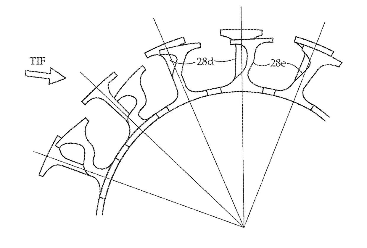
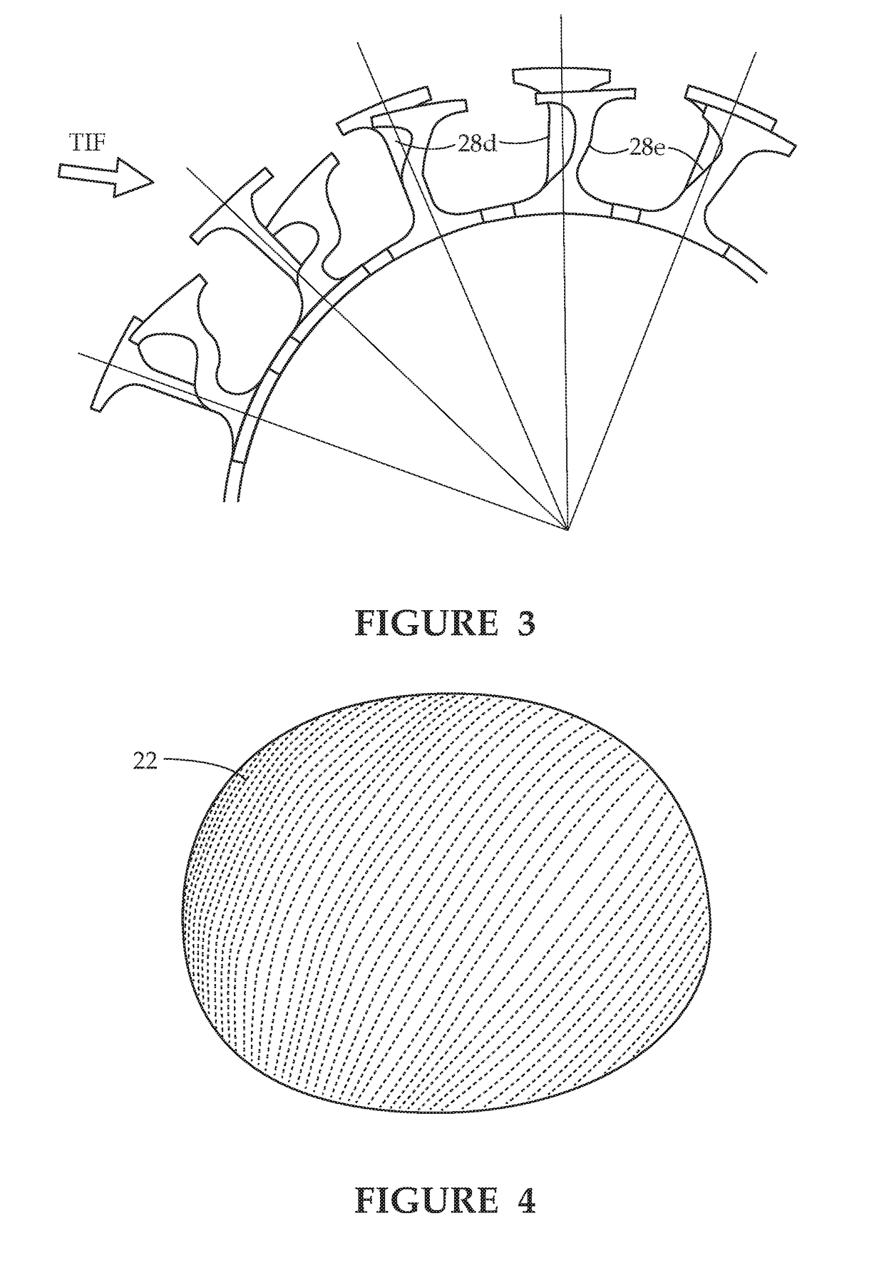
[0051]A helmet 20 (see FIGS. 14 and 15) incorporates a relatively hard outer shell 22 that can withstand the impacts that are applied on it, and a relatively soft inner layer or shell 24 that fits comfortably onto the head HD of a user (FIG. 16). Between the hard outer layer or shell 22 and the soft innermost interior layer of shell 24 resides an impact-absorbing layer 26 in the form of a plurality of Doric-like columns 28 that are attached to the outer shell 22 and to a central interior shell 30.

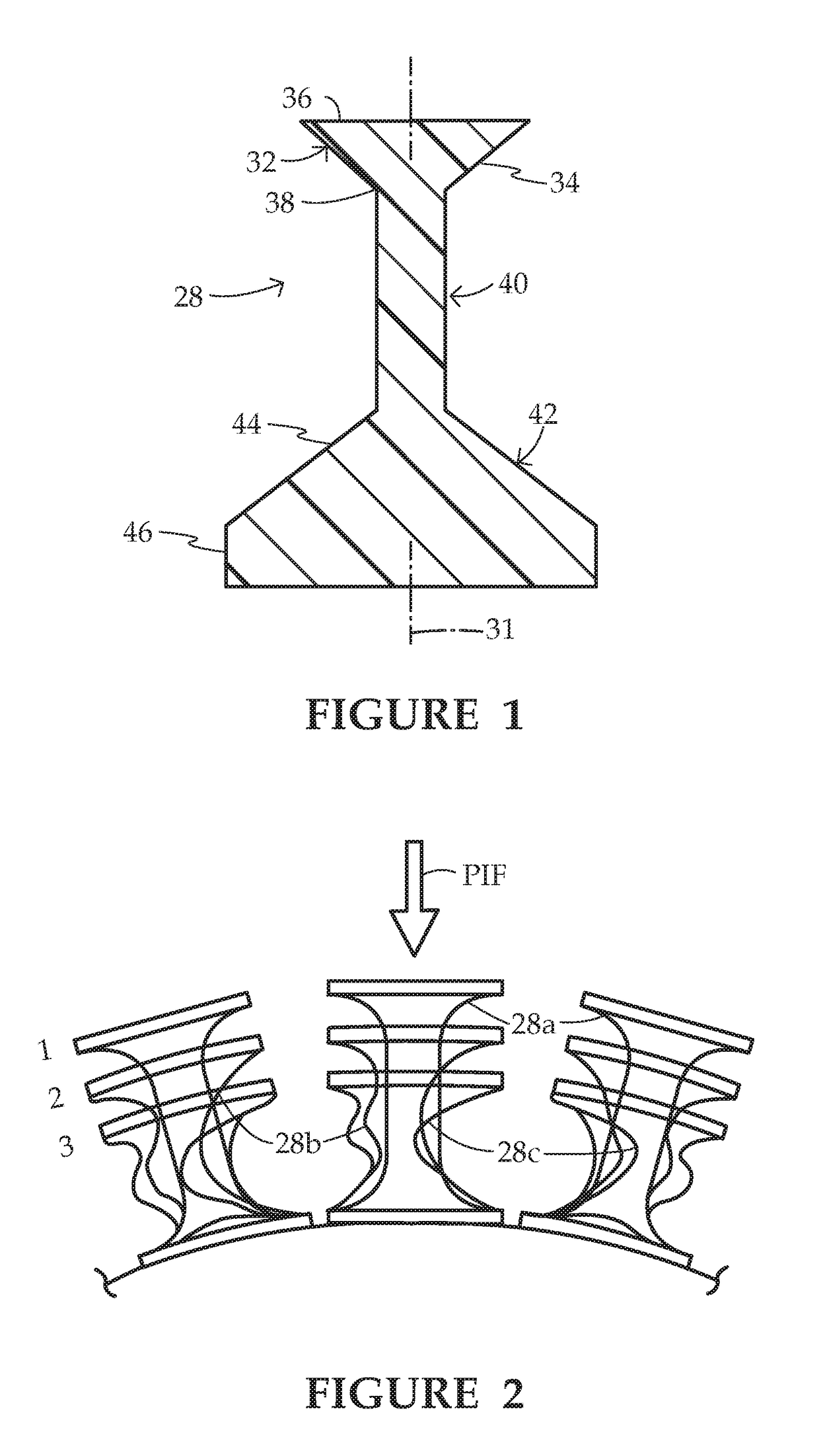
[0052]A preferred cross-section of such a (preferable axially symmetric) column 28 is shown in FIG. 1. The column 28 has a longitudinal axis 31 and includes three sections, namely, an upper section or capital 32, a cylindrical middle shaft or post section 40, and a lower section or base 42. Upper section or capital 32 has a conically tapered outer surface 34 bounded by a wide top or upper end 36 and a narrow bottom or lower end 38. Base section 42 has a conical outer surface 44 and a cylind...


PUM

PropertyMeasurementUnit
Forceaaaaaaaaaa
Dimensionaaaaaaaaaa
Heightaaaaaaaaaa

Abstract

A helmet has inner and outer shells separated by a plurality of interconnected relatively soft columns or posts. The columns each have a middle post or pillar section, a capital that is of larger diameter than the post, and a base also of larger transverse dimension than the post. When an impact above a design threshold occurs on the outer shell, the columns, particularly the post sections thereof, near the impact location compress and buckle, dissipating impact kinetic energy, while columns spaced from the impact zone stretch and support more of the impact force. The applied force is therefore reduced and spread out over a relatively large area, and a resultant wave created within the column manifold disperses additional heat, further reducing the force and torque applied on the outer shell and transmitted to the inner shell and onto the skull of a helmet user. A method and mold for fabricating the column manifold are also disclosed.

Description

BACKGROUND OF THE INVENTION[0001]The present invention is directed to helmets and to an associated method for manufacturing the helmets.[0002]The need for more protective helmets has been well documented. The frequent concussions encountered by football players have led to serious medical issues, have been the subject of numerous articles, and have given rise to lawsuits from injured players, a decline in television viewership, and a decline in participation at the youth level. Until recently, almost all helmets consisted of an exterior hard shell with softer padding attached to the inner surface of the shell. The concussion epidemic has led to the introduction of improved helmets that replace the conventional inner padding with more energy dissipating materials and constructions, but, judging from the fact that concussions continue to frequently occur in football and other sports, there is obviously much room for improvement.[0003]The prior art consists of the use of more energy ab...

Claims


Application Information

Patent Timeline
IPC IPC(8): A42B3/06A42B3/12B32B3/18B32B5/18B32B9/02B32B9/04B32B25/08B32B25/20B32B27/08B32B27/06B32B27/18B32B27/40B32B27/34B32B37/18B32B38/18B29C33/00
CPCA42B3/064A42B3/125B32B3/18B32B5/18B32B9/025B32B9/046B32B9/045B32B25/08B32B25/20B32B27/08B32B27/065B32B27/18B32B27/40B32B27/34B32B37/185B32B38/1866B29C33/0022A42B3/08B32B2266/0278B32B2305/022B32B2307/56B32B2317/08B32B2319/00B32B2375/00B32B2377/00B32B2437/04B32B2571/00B29K2083/005B29L2031/4821A42B3/065A42B3/124B29C33/0027B32B1/00B32B3/20B32B3/266B32B5/02B32B5/245B32B5/26B32B7/06B32B9/047B32B25/10B32B27/12B32B2250/05B32B2260/021B32B2260/046B32B2262/0269B32B2262/0292B32B2262/101B32B2262/106B32B2307/302B32B2307/536B32B2307/54B32B2307/544B32B2307/546B32B2307/558B32B2307/7145B32B2307/72
Inventor BRANDT, RICHARD A.SCEPANOVIC, DRAGOSLAV
Owner BRANDT RICHARD A
Learn More